
Drill String and Air Path Review
The drill string carries mechanical load and compressed air while its outside geometry shapes the return-flow path. A pipe-body calculation alone cannot approve the rig, threads, adapters, hammer and drilling arrangement. This guide brings together geometry, loads, pressure loss, inspection and acceptance evidence so the air path and mechanical path can be reviewed as one system.
Boundaries of the drill string calculations
The geometry, axial stress, torsion and bending examples below describe ideal uniform tube bodies. Tool joints, threaded transitions, wear, local stress concentration, pressure stresses, dynamic loading and fatigue require separate assessment. A nominal von Mises result cannot establish a real component’s service rating or remaining life.
Where the simple combined-stress relationship uses one normal and one shear stress, it excludes a general three-dimensional pressure-stress state. The Euler expression describes an ideal unsupported elastic column with declared end conditions; it must not be used as a field buckling limit for a confined, curved or contacting drill string.
The pressure-loss expression is a local Darcy–Weisbach form. Declare a Darcy friction factor and the local actual velocity and density. Significant gas expansion, temperature change or choking requires an appropriate compressible-flow treatment. Every connector, valve, swivel and adapter belongs in the air-path review. The pressure budget must avoid counting exhaust-side backpressure twice.
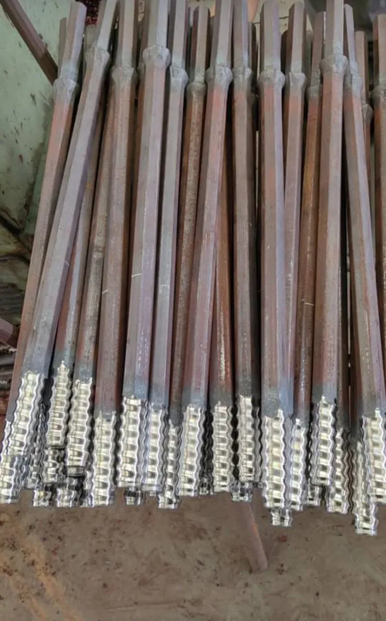
Epiroc’s DTH catalogue separately specifies pipe geometry, joints, threads, mass and adapters [V2]. Those product-specific values govern identification and compatibility. A typical API label, nominal diameter or a geometric calculation does not establish interchangeability or allowable make-up torque.
The illustrative 102 mm OD and 76 mm ID tube gives a 13 mm wall, steel area 0.003635 m², ideal mass about 28.53 kg/m at an assumed steel density of 7,850 kg/m³, and polar second moment approximately . These checks exclude tool-joint mass. Manufacturer component masses and ratings must be used for the actual rig assessment.
Detailed engineering guidance
- Drill string geometry and mechanical loading
- 1 The Complete DTH Drill String Function
The DTH drill string must:
- support its own weight
- transmit rotation
- transmit feed/pullback forces
- withstand bending
- tolerate vibration and impact
- maintain connection integrity
- deliver compressed air
- support the hammer
- maintain suitable annular geometry
- survive repeated make-up/break-out cycles
Therefore:
2 Drill String Architecture
A typical system may include:
↓
↓
↓
↓
↓
↓
↓
↓
Every connection forms part of both:
- the mechanical load path
- the pneumatic flow path
3 Primary Drill Pipe Dimensions
The principal dimensions are:
Outside Diameter
Inside Diameter
Wall Thickness
For a nominal uniform tube:
These dimensions control several competing engineering effects.
4 Why Outside Diameter Matters
Drill-pipe OD affects:
- cross-sectional steel area
- stiffness
- strength
- weight
- annular area
- borehole clearance
- for fixed bore diameter
- This can increase average annular return velocity
5 Why Inside Diameter Matters
Drill-pipe ID controls the internal compressed-air flow area:
For actual internal volumetric flow:
Therefore:
for unchanged actual flow.
Higher internal velocity can increase frictional pressure loss.
6 Why Wall Thickness Matters
Wall thickness affects:
- axial load capacity
- torsional capacity
- bending stiffness
- wear allowance
- mass
But increasing wall thickness while holding OD constant reduces:
which can increase pneumatic restriction.
Therefore:
automatically.
7 Drill Pipe Cross Sectional Steel Area
For a hollow circular pipe:
This area is fundamental to:
- axial stress
- pipe mass
- tensile-load calculations
8 Worked Steel Area Example
Assume:
Then:
Therefore:
9 Drill Pipe Mass per Unit Length
If steel density is:
then idealized pipe mass per unit length is:
Actual drill-pipe mass should preferably come from verified manufacturer data because:
- tool joints
- upset ends
- threads
- wear features
- can materially alter mass
10 Worked Mass Example
Using illustrative:
and:
then:
A 6 m idealized tube section would therefore contain approximately:
of steel before accounting for actual connection geometry.
11 String Weight Increases With Depth
For drill-string length:
idealized mass:
Weight:
Therefore:
Deep drilling progressively increases the suspended mechanical load.
12 Worked 300 m String Example
Using:
and:
Weight:
before including:
- hammer
- bit
- adapters
- actual joint mass
13 Worked 500 m String Example
At:
Therefore:
This illustrates how depth directly changes drill-string structural loading.
14 Top Connection Sees the Greatest Suspended Weight
In a vertical suspended string, the uppermost section supports approximately the weight of everything below it.
Therefore axial tensile loading generally increases toward the top of the string.
Conceptually:
is greatest near the surface under suspended conditions.
This makes upper-string and connection integrity particularly important during pulling operations.
15 Axial Stress
For axial force:
and effective steel area:
nominal axial stress is:
This is a simplified nominal stress.
Actual stresses can be higher around:
- threads
- shoulders
- geometric transitions
- wear damage
16 Worked Axial Stress Example
Suppose tensile load:
and:
Then:
This should not be compared directly with a generic steel strength to approve a real drill string.
Actual pipe grade, connection geometry, fatigue, wear and manufacturer ratings remain controlling.
17 Static Strength Is Not Enough
A drill string experiences repeated dynamic loading from:
- rotation
- vibration
- impact transmission
- bending
- make-up/break-out
- feed changes
Therefore a pipe that passes a simple static tensile calculation may still fail from:
or:
18 Tensile Load During Pullback
During withdrawal, the rig may need to overcome:
conceptually.
If cuttings accumulation or borehole instability increases:
the required pullback force can rise sharply.
19 Drill String Weight and Water
When submerged, the effective apparent weight of components can be reduced by buoyancy.
Conceptually:
and:
However, borehole friction, cuttings and hydraulic effects can still make extraction more difficult despite buoyancy.
20 Buoyancy Does Not Mean Easy Pullback
A water-filled bore may reduce apparent string weight but simultaneously increase:
- cuttings packing
- wall instability
- hydraulic effects
Therefore:
necessarily.
21 Feed Force
DTH drilling requires controlled feed force to maintain suitable bit-rock contact.
The drill string transmits this force from the feed system to the hammer.
Too little effective feed can cause:
- poor energy transfer
- unstable drilling
Excessive feed can increase:
- bending tendency
- bit loading
- deviation
- component stress
22 Compression in the Drill String
During drilling, parts of the string may experience compressive loading from feed force.
Therefore:
can exist even though the same string experiences tension during lifting.
The loading condition changes throughout the drilling cycle.
23 Tension vs Compression
A drill string is therefore not simply a tensile member.
It cycles between combinations of:
This combined loading drives fatigue and connection design.
24 Rotation Torque
The drill string transmits rotary torque:
from the rig to the hammer/bit assembly.
Torque is required to:
- rotate the bit
- index buttons
- overcome friction
Torque demand depends on:
- hole diameter
- formation
- bit condition
- cuttings
- deviation
- depth
25 Polar Moment of Inertia
For a hollow circular pipe:
This geometric property governs torsional stress and torsional stiffness.
Because diameter appears to the fourth power, geometry strongly influences torsional behaviour.
26 Nominal Torsional Shear Stress
For torque:
the maximum nominal torsional shear stress at the outer surface is:
This equation applies to an idealized tubular section.
Threaded connections require separate connection-specific evaluation.
27 Worked Torsional Example
Using:
first:
Approximately:
If:
then:
This is an illustrative nominal pipe-body calculation.
28 Torque Can Increase During Poor Cleaning
If cuttings accumulate:
Therefore a torque increase can simultaneously indicate:
- higher mechanical stress
- deteriorating hole cleaning
29 Torque Spike
A sudden torque spike can arise from:
- bit binding
- cuttings packing
- borehole instability
- mechanical obstruction
- High transient torque can be more damaging than a stable average torque
- Therefore maximum recorded torque matters alongside average torque
30 Torsional Stiffness
Angular twist for an ideal uniform tube can be approximated as:
Where:
= twist angle,
= torque,
= string length,
= shear modulus,
= polar moment.
Thus:
for otherwise unchanged conditions.
31 Deep Strings Store Torsional Energy
Because long drill strings twist elastically, they can store torsional energy.
Changing downhole resistance can lead to:
- torsional oscillation
- stick-slip-type behaviour
- torque fluctuations
Therefore deep drilling requires controlled rotation and attention to torque trends.
32 Stick Slip Concept
Conceptually:
can temporarily slow or stop downhole rotation while the string continues storing torsional energy.
When resistance is overcome, stored energy can release.
The exact dynamics depend on the drilling system.
33 Stick Slip Consequences
Potential consequences include:
- connection loading
- bit wear
- torsional fatigue
- unstable drilling
Stable torque transmission is therefore preferable to repeated severe torque cycling.
34 Bending
The drill string can bend because of:
- feed force
- borehole deviation
- gravity in inclined holes
- formation deflection
- unsupported length
- Bending introduces tensile stress on one side and compression on the other
35 Second Moment of Area
For a hollow circular pipe:
For a circular tube:
This geometric property governs bending stiffness.
36 Bending Stress
For bending moment:
nominal maximum bending stress is:
Again, this applies to an idealized pipe body.
Connections and worn sections can have different local stress behaviour.
37 Combined Axial and Bending Stress
At a critical surface:
One side may experience higher tension while the opposite side experiences reduced tension or compression.
This alternating stress is important for fatigue.
38 Combined Stress With Torsion
For a simplified ductile-material assessment, combined loading may be represented using an equivalent-stress concept such as von Mises stress:
for the simplified combination of normal and torsional shear stress.
Real drill-string qualification must use actual component and connection ratings.
39 Worked Combined Stress Concept
Suppose nominal combined normal stress is:
and torsional shear stress:
Then:
This is illustrative only and is not a standalone acceptance criterion.
40 Buckling
A slender member under compression can become unstable before material yield occurs.
The classic ideal Euler critical load is:
Where:
= Young’s modulus,
= second moment of area,
= unsupported length,
= effective-length factor.
Bending buckling connections and fatigue
41 Euler Buckling Is a Conceptual Limit
A real DTH drill string is constrained by:
- borehole wall
- joints
- curvature
- contact
- rotation
Therefore a simple free-column Euler calculation does not directly describe the complete downhole buckling behaviour.
It remains valuable for understanding why:
and:
increase buckling sensitivity.
42 Buckling and Feed Force
Excessive compressive feed can encourage lateral deflection.
Therefore:
beyond the hammer/bit’s appropriate operating requirement.
Feed should support efficient impact transfer without unnecessarily loading the drill string in compression.
43 Buckling and Hole Deviation
A buckled or laterally deflected string can increase:
- bore-wall contact
- friction
- deviation tendency
- bending fatigue
- rotational resistance
- connection loading
Thus feed-force management contributes to hole quality as well as mechanical reliability.
A useful principle is:
but:
The correct feed depends on the hammer, bit, formation, drill-string configuration and manufacturer operating guidance.
44 Drill String Slenderness
For an ideal structural member, slenderness ratio can be represented as:
Where:
= effective-length factor,
= relevant unsupported length,
= radius of gyration.
The radius of gyration is:
Higher slenderness generally increases susceptibility to elastic instability under compression.
45 Radius of Gyration for Hollow Pipe
Using:
and:
then:
For a hollow circular section this simplifies to:
for the ideal uniform tube.
46 Worked Radius of Gyration Example
Using:
This provides a useful geometric measure of bending resistance relative to cross-sectional area.
47 Borehole Confinement Changes Buckling Behaviour
A deep drill string is not normally a freely unsupported column over its complete length.
The borehole constrains lateral displacement.
Therefore real downhole behaviour can involve:
- sinusoidal contact
- helical contact
- distributed bore-wall reactions
Detailed analysis can require specialized drill-string mechanics rather than simple Euler theory.
48 Sinusoidal Buckling Concept
Under increasing compression, a constrained string may begin contacting the bore wall in a wave-like pattern.
This can increase:
and therefore:
The result can be reduced transmission of surface feed to the hammer.
49 Helical Buckling Concept
At greater compressive loading, the drill string can potentially adopt a more severe helical contact pattern.
Consequences can include:
- higher friction
- greater torque
- increased wear
- reduced effective weight/feed transfer
- The exact threshold depends on geometry, inclination and loading
50 Surface Feed Is Not Necessarily Bit Feed
Because of:
- friction
- buckling
- bore-wall contact
surface feed force:
may not equal force reaching the hammer:
Conceptually:
This becomes increasingly important with depth and deviation.
51 Weight on Bit Concept
In DTH drilling, bit loading must remain compatible with effective hammer operation.
Unlike some rotary drilling methods, simply maximizing:
does not guarantee higher penetration.
The DTH hammer provides the primary percussive energy.
Feed primarily maintains suitable contact and drilling control.
52 Excessive Feed Consequences
Potential consequences include:
- bit-button overload
- poor indexing
- string compression
- increased deviation
- connection stress
- higher rotational resistance
- Therefore feed should be optimized rather than maximized
53 Insufficient Feed Consequences
Too little feed can cause:
- poor bit-rock contact
- unstable hammer/bit behaviour
- inefficient energy transfer
- excessive vibration
- The optimum lies within an equipment- and formation-specific operating window
54 Drill String Neutral Point
In some operating conditions, part of the string may be in tension while another part is in compression.
The transition is conceptually a:
Its position can change with:
- string weight
- feed
- inclination
- friction
- buoyancy
Understanding this concept helps explain why different sections experience different loading.
55 Neutral Point Moves With Feed
Increasing downward feed can increase the length of string experiencing compression.
Therefore:
can move the neutral point upward.
This may increase the portion of the string exposed to buckling-related contact.
56 Deep Hole Friction
Drill-string contact with the bore wall generates friction.
A simplified relationship is:
Where:
= effective friction coefficient,
= normal contact force.
Real downhole friction is more complex because contact forces vary continuously.
57 Friction Increases Pullback Requirement
During withdrawal:
Therefore a string that weighs 100 kN may require substantially more than 100 kN of pullback under adverse borehole conditions.
Rig pullback capacity must account for credible operating loads.
58 Pullback Reserve
A rig should not be selected so that:
with virtually no reserve.
Credible allowances may be required for:
- friction
- cuttings
- water
- bore irregularity
However, reserve should not be interpreted as permission to apply unlimited force to stuck tooling.
59 Stuck String Load
If the drill string becomes stuck, pulling force can increase rapidly.
The load path includes:
The weakest component or connection can govern allowable recovery load.
60 Recovery Force Must Respect Ratings
Never assume that available rig pullback can safely be applied fully to the drill string.
Verify:
- pipe tensile rating
- connection rating
- adapters
- top-drive components
- hammer connection
- Equipment ratings—not rig capability alone—control permissible recovery loading
61 Torque Rating Must Also Be Respected
Likewise:
may exceed the safe torque rating of:
- drill pipe
- connections
- adapters
Therefore:
subject to manufacturer ratings.
62 Connections Often Govern
The pipe body may have substantial strength while the threaded connection experiences:
- stress concentration
- repeated make-up
- wear
- impact
- bending
Therefore drill-string integrity cannot be established from pipe-body calculations alone.
63 Connection Functions
A drill-pipe connection must simultaneously:
- transmit axial load
- transmit torque
- maintain alignment
- resist loosening
- maintain pneumatic sealing
- survive repeated assembly cycles
- This makes connection engineering central to deep DTH reliability
64 Thread Geometry
Connection performance depends on factors such as:
- thread form
- pitch
- flank geometry
- root geometry
- shoulder design
- engagement length
- Actual allowable loads must come from the connection manufacturer
- Generic thread calculations should not replace verified ratings
65 Thread Root Stress Concentration
Threads create geometric discontinuities.
Local stress at a thread root can substantially exceed nominal pipe-body stress.
Conceptually:
Where:
= stress concentration factor.
The actual factor depends on connection geometry.
66 Fatigue Initiation at Connections
Repeated stress cycles combined with stress concentration can initiate fatigue cracks at:
- thread roots
- shoulders
- upset transitions
- damaged surfaces
- Therefore connection inspection is essential in high-cycle drilling
67 Make Up Integrity
Connections require correct assembly to maintain:
- torque transfer
- axial integrity
- sealing
- alignment
Insufficient make-up can permit:
- loosening
- fretting
- leakage
Excessive make-up can damage:
- threads
- shoulders
- connection geometry
- Use manufacturer-specified procedures
68 Connection Make Up Torque
Do not invent a universal make-up torque.
The correct value depends on:
- connection design
- diameter
- material
- lubrication
- manufacturer specification
Therefore:
for the actual connection.
69 Thread Lubrication
Where specified, correct thread compound/lubrication influences:
- friction
- make-up torque
- galling
- disassembly
Using an inappropriate compound can change the relationship between applied torque and connection preload.
Follow connection-manufacturer requirements.
70 Dirty Threads
Contamination with:
- grit
- rock dust
- damaged metal
- corrosion products
can cause:
- poor make-up
- galling
- accelerated wear
- leakage
- Thread cleanliness is therefore both a mechanical and pneumatic requirement
71 Damaged Threads
Potential damage includes:
- flattened crests
- torn material
- galling
- cracks
- deformation
- A connection that can still be forced together is not necessarily serviceable
- Inspection criteria should govern continued use
72 Connection Leakage
A damaged or poorly made-up connection can leak compressed air.
Therefore connection failure can produce two simultaneous problems:
Mechanical
Reduced structural integrity.
Pneumatic
and potentially:
This makes joint condition critical in deep drilling.
73 Cumulative Joint Leakage
A small leak at one joint may appear insignificant.
But a deep string can contain many connections.
Conceptually:
As:
the potential cumulative leakage burden increases.
74 Number of Connections
For nominal pipe length:
and string length:
approximate pipe count is:
The number of connections is of the same order, depending on assembly architecture.
75 Worked Connection Count
Suppose:
and each pipe is:
Then:
A 360 m string therefore contains dozens of threaded interfaces whose mechanical and pneumatic condition matter.
76 Deep Hole Connection Reliability
If each connection has even a small probability of developing a problem, increasing connection count increases overall exposure.
Therefore deep drilling requires:
- consistent make-up
- inspection
- thread protection
- damaged-joint removal
77 Connection Cycle Count
Each pipe can experience repeated:
- make-up
- drilling
- break-out
- handling
- Track service exposure where practical
A connection’s condition depends not only on drilled metres but also on assembly cycles.
78 Fatigue
Fatigue is progressive damage under repeated fluctuating stress.
Drill-string fatigue can be driven by:
- rotation under bending
- vibration
- torque cycling
- axial cycling
- connection stress concentration
- Failure can occur at stresses below static ultimate strength
79 Rotating Bending Fatigue
If a bent pipe rotates, a point on its surface alternates between:
- tension
- compression
- This produces a repeated stress cycle
- Therefore pipe straightness is critical to fatigue life
80 Bent Drill Pipe
A bent pipe can cause:
- vibration
- eccentric rotation
- bore-wall contact
- connection loading
- hole deviation
- fatigue
- It should be evaluated against appropriate straightness/rejection criteria
Wear inspection handling and asset history
81 Runout
Pipe straightness may be evaluated through runout measurements where appropriate.
Excessive runout indicates geometric deviation from a straight rotational axis.
Manufacturer or fleet inspection criteria should define acceptable limits.
82 Fatigue Crack Growth
A small crack can grow under repeated loading.
Conceptually:
The final fracture event may appear sudden even though damage accumulated over many drilling cycles.
83 Surface Damage as Crack Initiator
Potential fatigue initiation sites include:
- gouges
- corrosion pits
- thread damage
- wear grooves
- weld defects where applicable
- Therefore surface condition matters beyond appearance
84 Notches and Stress Concentration
A local notch increases stress concentration.
Conceptually:
Therefore a deeply gouged pipe can have substantially higher local stress than nominal calculations suggest.
85 Wear Reduces Wall Thickness
If wall thickness decreases:
then:
- steel area decreases
- torsional capacity decreases
- bending stiffness decreases
- Wear therefore progressively changes the mechanical design of the pipe
86 Remaining Wall Thickness
If original wall thickness is:
and measured material loss is:
then:
Whether that remaining thickness is acceptable must be determined from approved inspection/rejection criteria.
87 Wear Percentage
A monitoring metric is:
This does not itself establish a universal rejection threshold.
88 OD Wear
External abrasion can reduce:
and alter:
- wall thickness
- section modulus
- annular geometry
Therefore heavily worn pipe affects both mechanical strength and borehole hydraulics.
89 ID Wear Erosion
High-velocity compressed air carrying contamination can contribute to internal erosion in susceptible regions.
Internal wear can change:
- wall thickness
- internal roughness
- connection condition
- Inspection strategy should reflect actual service severity
90 Tool Joint Wear
Tool joints can experience concentrated:
- bore-wall contact
- rotation
- abrasion
Because joint geometry often differs from pipe body geometry, tool-joint wear should be inspected separately.
91 Wear and Annular Area
If tool-joint OD changes with wear, local annular geometry also changes.
However, mechanical integrity normally dominates the wear decision.
A worn connection should never be retained merely because it increases annular clearance.
92 Corrosion
Where moisture and environmental conditions permit, corrosion can cause:
- general wall thinning
- localized pitting
- thread damage
Pitting is particularly important because it can create local stress concentration.
93 Corrosion Fatigue
Corrosion and cyclic stress can interact.
A corrosion pit can become a fatigue initiation site.
Therefore long-term storage and maintenance practices can influence future drill-string reliability.
94 Storage
Drill pipe should be stored to minimize:
- contamination
- water retention
- thread damage
- uncontrolled corrosion
- bending
- Thread protectors should be used where specified
95 Handling Damage
Common handling hazards include:
- dropping pipe
- striking threads
- dragging connections
- improper lifting
- Handling damage can create defects before the pipe even enters the borehole
96 Pipe Handling Is Reliability Engineering
The lifecycle is:
Reliability must be controlled through the entire cycle.
97 Connection Protection During Handling
Exposed threads should be protected against:
- impact
- dirt
- moisture
A damaged connection can later cause:
- leakage
- difficult make-up
- mechanical failure
98 Pipe Identification
For large fleets, each pipe can be assigned a unique ID.
Track:
- purchase date
- specification
- drilling metres
- inspections
- repairs
- rejection
- This creates a drill-string asset history
99 Drill Pipe Register
A controlled register can include:
Pipe ID | OD | ID | Length | Service Metres | Connection Condition | Wall Condition | Status |
|---|---|---|---|---|---|---|---|
DP001 | — | — | — | — | — | — | PASS |
DP002 | — | — | — | — | — | — | REVIEW |
DP003 | — | — | — | — | — | — | REJECT |
This supports lifecycle management.
100 Rotation of Pipe Position
If operationally appropriate and permitted by the equipment system, pipe positions within a string can be managed to avoid repeatedly exposing the same components to the most severe positions.
Any such fleet practice should follow manufacturer and site procedures.
101 Upper vs Lower String Exposure
Different string locations experience different conditions.
Upper String
May experience greater suspended tensile load.
Lower String
May experience stronger hammer-related vibration and abrasive borehole conditions.
Therefore wear/failure mechanisms can vary by position.
102 Bottom Hole Components
The lower assembly may include:
- hammer
- bit
- sub/adaptor
- stabilizing components where applicable
- lowest drill-pipe connections
These components experience a demanding combination of:
Therefore lower-string inspection deserves particular attention.
103 Hammer to Pipe Connection
The connection between the drill string and hammer must:
- transmit torque
- transmit axial loading
- maintain alignment
- retain pneumatic sealing
- tolerate vibration
- An unsuitable or damaged adapter can compromise the entire drilling system
104 Adapter Engineering
Adapters should be verified for:
- thread compatibility
- pressure rating
- torque rating
- axial-load rating
- bore/internal flow area
An adapter that is mechanically compatible but internally restrictive can increase:
and reduce hammer performance.
105 Internal Bore Continuity
The compressed-air path should be evaluated through:
The smallest significant internal restriction can become a pneumatic bottleneck.
106 Minimum Internal Flow Area
Define:
The local velocity at this restriction is:
at the relevant actual-flow condition.
High local velocity can create disproportionate pressure loss.
107 Connection Bore Restriction
A pipe may have:
while a connection reduces effective bore to:
Area ratio:
Thus the connection provides only about 60.5% of the pipe’s internal flow area.
108 Velocity Through Restriction
For the same actual volumetric flow:
Therefore:
The local velocity becomes approximately 65% higher.
This demonstrates why connection-bore geometry matters in high-flow DTH systems.
109 Local Pressure Loss
Restrictions create local pressure loss.
Conceptually:
Where:
= local loss coefficient,
= local fluid density,
= appropriate local velocity.
For high-pressure compressible air, detailed calculation requires an appropriate compressible-flow treatment.
110 Many Small Restrictions Can Accumulate
For multiple connections:
Therefore deep strings with many joints can accumulate meaningful connection-related pressure loss.
This links mechanical connection design directly with compressor sizing.
111 Pipe Friction Pressure Loss
A general Darcy-Weisbach form is:
for an appropriate flow treatment.
Where:
= friction factor,
= length,
= internal diameter.
For high-pressure compressed air, density changes along the pipe, so a simple constant-density calculation is only an approximation.
112 Length Effect
Conceptually:
Therefore deep drilling can progressively consume more of the source-pressure budget.
This is one reason compressor suitability must be checked at final depth.
113 Diameter Effect
For a given mass flow:
can cause a strong increase in:
- velocity
- frictional pressure loss
Thus small changes in internal diameter can materially affect deep-hole pneumatic performance.
114 Roughness
Internal roughness influences:
and therefore pressure loss.
Potential contributors include:
- corrosion
- scale
- damage
- manufacturing condition
A heavily degraded internal surface may therefore create both mechanical and pneumatic consequences.
115 Reynolds Number
For fluid flow:
Where:
= dynamic viscosity.
Reynolds number helps characterize flow regime.
High-flow compressed-air drilling systems commonly involve turbulent conditions, but the actual state should be calculated where detailed analysis is required.
116 Friction Factor
For turbulent flow, friction factor depends on:
and relative roughness:
Appropriate correlations or engineering software can be used.
Do not assume one friction factor for every pipe size, pressure and flow.
117 Compressibility
As compressed air travels down the drill string:
- pressure decreases
- density changes
- velocity can change
Therefore:
for rigorous analysis.
Deep high-pressure systems may require compressible-flow calculations rather than ordinary incompressible pipe-flow assumptions.
118 Pneumatic Pressure Profile
Conceptually:
decreases from the surface source toward the hammer due to:
- pipe friction
- connection losses
- fittings
The objective is to ensure:
as applicable.
119 Drill String Pressure Budget
flow.
120 Pressure Loss Measurement
Where practical:
can identify surface-system loss.
Downhole drill-string loss may then be estimated from:
- calculation
- manufacturer data
- controlled testing
- Direct bottom-hole pressure measurement may not always be practical
Internal airflow and pressure loss
121 Pressure Loss per Unit Length
A project-specific trend may be represented as:
but this should not automatically be assumed constant because:
- density changes
- flow changes
- connections accumulate
- pressure changes
- Use it cautiously for trending rather than universal prediction
122 Pressure Loss vs Depth Trend
Track:
If measured/estimated loss rises faster than expected, investigate:
- internal restriction
- leakage
- damaged pipe
- connection problems
- changed airflow
- This can provide early warning of drill-string deterioration
123 Internal Leakage
A cracked pipe or damaged connection can release compressed air before it reaches the hammer.
Then:
conceptually.
Deep-string leakage can be difficult to identify because the air may still return through the annulus.
124 Leakage Symptoms
Potential symptoms include:
- compressor remains heavily loaded
- drill-head pressure appears reasonable
- hammer performance declines
- surface air return remains substantial
- This pattern can warrant investigation of drill-string integrity
125 Connection Leakage vs Pipe Body Leakage
Leakage can originate from:
Connections
thread damage,
poor make-up,
seal/interface damage.
Pipe Body
crack,
erosion,
perforation.
The repair/rejection decision depends on the component and approved maintenance procedure.
126 Pneumatic Leak Test
Any pressure/leak testing of drill-string components should follow approved equipment procedures and appropriate safety controls.
High-pressure compressed air testing can be hazardous.
Do not improvise unsafe pressurization methods.
127 Drill Pipe OD and Annular Return
The external side of the pipe controls:
Thus drill-pipe sizing simultaneously affects:
Downward Flow
through:
Upward Return
through:
128 Larger OD Return Side Effect
For fixed hole diameter:
Therefore for unchanged actual return flow:
This can support cuttings transport.
But mechanical clearance and borehole conditions must remain acceptable.
129 Larger ID Supply Side Effect
For fixed air mass flow:
generally reduces:
- internal velocity
- frictional pressure loss
Therefore a pipe with suitable large internal area can preserve more source pressure for the hammer.
130 Ideal Pneumatic Direction
From a purely pneumatic perspective one might want:
and:
because this can:
- reduce internal loss
- reduce annular area
But this leaves less wall thickness:
unless overall pipe size increases.
Mechanical strength and rig compatibility therefore constrain the pneumatic optimum.
131 Drill Pipe Optimization Problem
The true design is:
subject to:
- hole diameter
- rig capability
- hammer
- depth
- connection system
- This is a multi-variable engineering problem
132 Worked Pipe Comparison
Consider two simplified pipe bodies.
Pipe A
Pipe B
Pipe B provides greater internal flow area but less steel area.
Therefore:
- pneumatic pressure loss may improve
- structural capacity may decrease
- The actual selection requires verified manufacturer ratings
133 Internal Area Comparison
Pipe A:
Pipe B:
Area increase:
134 Steel Area Comparison
Pipe A:
Pipe B:
Thus Pipe B has substantially less steel cross-sectional area.
This illustrates the mechanical-pneumatic trade-off.
135 Wall Thickness Comparison
Pipe A:
Pipe B:
The larger internal bore has been obtained by reducing wall thickness.
Whether this is acceptable cannot be determined from airflow considerations alone.
136 Weight Comparison
Because:
Pipe B is lighter.
This can reduce:
- suspended string weight
- handling load
But lower steel area may reduce:
- tensile capacity
- torsional capacity
- wear allowance
- Again, verified product ratings govern
137 Mechanical Pneumatic Selection Matrix
Parameter | Larger Wall | Larger ID |
|---|---|---|
Steel area | Higher | Lower |
Weight | Higher | Lower |
Tensile potential | Higher | Potentially lower |
Torsional potential | Higher | Potentially lower |
Wear allowance | Higher | Lower |
Internal flow area | Lower | Higher |
Pressure loss | Potentially higher | Potentially lower |
This is conceptual; connection design and material grade can change the outcome.
138 Pipe OD Comparison
Now consider equal wall concept but different OD.
Larger OD can increase:
- stiffness
- section properties
- weight
- It also reduces annular area for a fixed bore diameter
But it may reduce:
- borehole clearance
- tolerance to deviation
- cuttings passage space
- Therefore larger OD is not automatically superior
139 Borehole Clearance
Radial clearance in a simplified concentric bore is:
If clearance becomes too small, cuttings transport and mechanical movement can become problematic.
The appropriate minimum clearance depends on the drilling system.
140 Worked Clearance Example
Hole:
Pipe:
Then:
This is nominal radial clearance for a perfectly concentric, gauge-size bore.
Actual local clearance can be much smaller because of:
- eccentricity
- deviation
- cuttings
- bore irregularity
141 Tool Joint Clearance
If tool-joint OD exceeds pipe-body OD, the minimum clearance may occur at the joint.
Therefore use:
when checking minimum mechanical clearance.
Do not use pipe-body OD alone.
142 Minimum Annular Gap
Conceptually:
for simplified concentric geometry.
This gap must remain compatible with:
- cuttings passage
- bore deviation
- mechanical movement
143 Bore Enlargement vs Clearance
Bore enlargement increases clearance but also increases:
which can reduce annular velocity.
Thus a larger-than-gauge hole may reduce mechanical contact while simultaneously worsening pneumatic cleaning.
144 Undergauge Hole
If the bore becomes effectively smaller because of:
- swelling
- collapse
- debris
- clearance decreases
This can increase:
- friction
- torque
- sticking risk
Therefore nominal bit diameter does not always represent actual downhole clearance.
145 Drill String Alignment
A straight, correctly assembled drill string supports:
- smoother rotation
- lower vibration
- better hole trajectory
- reduced connection loading
- Misalignment can increase bending stress and wear
146 Connection Shoulder Alignment
Where the connection design uses shoulders, proper contact can be important for:
- torque transfer
- alignment
- sealing
- Damaged or contaminated shoulders can compromise connection performance
- Use manufacturer inspection requirements
147 Cross Threading
Cross-threading can damage:
- thread flanks
- alignment
- sealing surfaces
A connection that has been cross-threaded should be inspected rather than simply tightened harder.
148 Galling
Galling is severe adhesive wear that can occur during threaded assembly/disassembly.
Potential contributors include:
- improper lubrication
- contamination
- damaged threads
- incorrect make-up
- Galled threads can compromise both mechanical integrity and sealing
149 Fretting
Small repeated relative movement at loaded contact surfaces can cause fretting damage.
Connections subjected to insufficient preload or vibration may be susceptible.
The actual mechanism depends on connection design and operating condition.
150 Thread Washout
Air leakage through a damaged connection can erode material over time.
This can enlarge the leakage path and progressively worsen:
Therefore a small connection leak should not automatically be considered harmless.
151 Progressive Leakage Failure
A possible sequence is:
↓
↓
↓
↓
↓
Early detection has both pneumatic and mechanical value.
152 Pipe Body Erosion
High-velocity leakage through a crack or defect can also enlarge local damage.
Therefore unexplained pneumatic deterioration should be investigated promptly.
153 Fatigue and Pneumatic Leakage Can Interact
A fatigue crack may initially create:
- small structural defect
- small air leak
- Continued cyclic loading and erosive flow can then worsen both
This is another reason deep-hole leakage should not be dismissed as merely an efficiency problem.
154 Connection Failure Consequence
A connection failure downhole can cause:
- loss of lower string
- fishing/recovery operation
- downtime
- bore abandonment
Therefore connection integrity can have extremely high consequence even when the component itself is inexpensive relative to the project.
155 Failure Criticality
A useful risk relationship is:
Even a low-probability connection failure may deserve strong preventive control because the consequence at great depth can be severe.
156 Failure Consequence Increases With Depth
A drill-string failure at:
and a failure at:
are not operationally equivalent.
As failure depth increases, potential consequences can include:
- longer fishing operations
- greater retrieval difficulty
- increased downtime
- higher risk of unrecovered tooling
- borehole deterioration during recovery
- possible redrilling
- possible bore abandonment
Therefore:
157 Drill String Reliability Philosophy
The objective should not be:
Instead:
The economic value of preventive inspection increases when retrieval consequences are severe.
158 Inspection Categories
A controlled drill-pipe inspection programme can include:
Visual Inspection
For:
- cracks
- gouges
- deformation
- corrosion
- thread damage
Dimensional Inspection
For:
- OD
- wall thickness
- straightness
- connection dimensions
Non Destructive Examination
Where specified for critical components.
Pneumatic Integrity
Where approved procedures exist.
Inspection depth should reflect:
- equipment type
- service severity
- manufacturer requirements
159 Visual Inspection
Before reuse, inspect for obvious evidence of:
- bending
- cracking
- severe abrasion
- damaged threads
- damaged shoulders
- corrosion
- deformation
- Visual inspection is valuable but cannot detect every subsurface defect
160 Wall Thickness Measurement
Where wall loss is important, ultrasonic or another appropriate thickness measurement method may be used by qualified personnel.
Record:
against:
Then:
Return geometry and drilling conditions
161 Remaining Wall Percentage
A monitoring parameter is:
Example:
Original:
Measured:
Then:
This percentage does not establish acceptance by itself.
Approved rejection criteria remain controlling.
162 Why Universal Wall Loss Limits Should Be Avoided
A statement such as:
“Reject every pipe after X% wall loss”
cannot be universally applied without considering:
- pipe design
- material
- connection
- rated loads
- manufacturer limits
163 Straightness Inspection
Straightness can be assessed by an appropriate:
- runout
- dimensional
- fixture-based method
A bent pipe can produce cyclic bending even if its wall thickness remains acceptable.
Thus:
164 Connection Inspection
Inspect:
- thread profile
- root condition
- crest damage
- galling
- shoulder condition
- deformation
- cracks
- sealing surfaces
Connections deserve independent disposition rather than being assumed acceptable because the pipe body passes.
165 Crack Inspection
For critical components, appropriate NDT may be specified to detect defects not reliably visible to the eye.
The appropriate method depends on:
- material
- component geometry
- expected defect orientation
- applicable inspection standard
166 Inspection Frequency
Inspection frequency should reflect:
- drilled metres
- connection cycles
- formation abrasiveness
- depth
- previous failures
- operating severity
A high-risk deep-hole programme may justify more intensive inspection than routine shallow work.
167 Event Triggered Inspection
Inspect after abnormal events such as:
- severe torque spike
- stuck-string recovery
- overpull event
- dropped pipe
- abnormal vibration
- suspected connection leakage
A component should not automatically return to service merely because drilling resumed successfully after the event.
168 Post Stuck Inspection
A stuck-string recovery can expose components to loads substantially above normal drilling conditions.
Therefore affected pipe and connections should be assessed against appropriate inspection requirements before routine reuse.
169 Overpull Record
Where rig instrumentation permits, record maximum recovery pull:
Then compare against approved:
- pipe
- connection
- adapter
- ratings
- This provides stronger evidence than relying only on operator recollection
170 Torque Event Record
Similarly record severe torque events:
and identify the pipes/connections involved where practical.
This can support targeted inspection.
171 Service History
For each pipe, useful history may include:
plus inspection results.
This creates a much stronger lifecycle record than age alone.
172 Pipe Life Is Not Simply Calendar Age
A relatively new pipe can accumulate severe service rapidly.
An older pipe may have low service exposure.
Therefore:
for maintenance decisions.
173 Metres Drilled per Pipe
Track:
where practical.
But drilled metres alone do not capture:
- torque severity
- abrasiveness
- connection cycles
- bending
- It is one exposure metric—not a complete life predictor
174 Connection Cycles per Pipe
A pipe used in shallow drilling can experience many make-up/break-out cycles despite relatively low total drilled metres.
Therefore:
can be important independently of:
175 Service Severity Index Conceptual
A fleet may create a project-specific severity classification using:
- depth
- torque
- formation
- connection cycles
- stuck events
For example:
Normal / Severe / Extreme
Such classifications should support inspection planning rather than claim a universal fatigue-life formula.
176 Drill Pipe Rotation Strategy
Where permitted by equipment procedures, fleet management may rotate pipe positions to distribute exposure.
The objective is to avoid repeatedly placing the same pipe in the most demanding:
- upper
- lower
- transition
- positions
- This is an asset-management practice rather than a substitute for inspection
177 New and Worn Pipe Mixing
Mixing components with substantially different:
- wear
- connection condition
- dimensions
- can create inconsistent string behaviour
- Compatibility should be checked before assembly
178 Dimensional Compatibility
Verify:
- connection type
- OD
- ID
- length
- shoulder geometry
A component that threads together is not automatically an approved compatible component.
179 Mixed Internal Diameters
If the string contains different IDs, the smallest section can become the principal pneumatic restriction.
Therefore:
subject to the actual geometry and length of each restriction.
180 Mixed Outside Diameters
Different ODs create varying annular areas:
This changes local return velocity.
Therefore mixed drill strings complicate both:
- supply-flow analysis
- return-flow analysis
181 Transition Components
Subs and adapters can create abrupt changes in:
- ID
- OD
These changes can introduce:
- pressure losses internally
- local annular-flow changes externally
Therefore transition components should be included in detailed pneumatic modelling.
182 Drill String Weight Calculation
For several component types:
Then:
This is preferable to using one approximate kg/m value when tool joints and heavy components materially affect total mass.
183 Complete Suspended Load
The rig may need to support:
before friction or recovery loads are considered.
184 Rig Pullback Gate
A basic selection condition is:
with appropriate engineering reserve.
But the rig’s available pullback must not exceed component ratings during actual recovery operations.
185 Feed Pullback Asymmetry
Rig:
and:
may differ.
Deep-hole selection should evaluate both.
A rig can have adequate drilling feed yet insufficient pullback for a deep loaded string.
186 Rotary Torque Gate
Likewise:
while:
must remain within the allowable limits of:
- drill pipe
- connections
- hammer/bit system
187 Rotary Speed
Rotation speed:
interacts with:
- bit indexing
- formation
- ROP
- vibration
- The correct rotational speed is hammer/bit/application-specific
- More RPM is not automatically better
188 Torsional Power
Mechanical rotational power is:
where:
for in rpm.
This connects rotary torque and speed to mechanical power.
189 Worked Rotary Power Example
Suppose:
and:
Then:
Therefore:
This is ideal mechanical rotational power at the stated torque and speed.
190 Rotation Energy Is Part of Total Drilling Energy
the drilling air and fuel-efficiency guide focused strongly on compressed-air energy.
The complete system also consumes energy through:
- rotation
- feed
- auxiliaries
Therefore:
The compressor remains dominant in many DTH applications, but the other terms should not be ignored in complete energy analysis.
191 Torque Increase Can Raise Energy Consumption
If cuttings accumulation causes:
then at constant rotational speed:
because:
Thus poor cleaning can increase both:
- compressor energy per metre
- rotary energy per metre
192 String Vibration
The drill string can experience:
- axial vibration
- torsional vibration
- lateral vibration
- These modes can interact
Vibration can accelerate:
- fatigue
- connection wear
- bore-wall contact
- tool damage
193 Axial Vibration
Hammer impacts create repeated axial excitation.
Although the hammer operates downhole, vibration can propagate through the string.
The response depends on:
- string length
- stiffness
- joints
- boundary conditions
194 Torsional Vibration
Changing rotational resistance can produce torque oscillations.
Potential sources include:
- irregular formation
- bit interaction
- cuttings accumulation
- bore-wall friction
Monitoring torque variability can therefore provide useful diagnostic information.
195 Lateral Vibration
Bending, eccentricity or pipe runout can create lateral vibration.
This can increase:
- bore-wall impact
- pipe wear
- connection stress
- hole deviation
- Straightness and alignment are therefore important
196 Resonance Concept
Any mechanical system has natural frequencies.
If excitation approaches a natural mode:
vibration amplitude can increase.
Detailed dynamic analysis may be required for severe recurrent vibration problems.
197 Do Not Diagnose All Vibration as Resonance
Vibration can also arise from:
- bent pipe
- worn bit
- loose connection
- poor feed
- irregular formation
Resonance should be diagnosed from evidence rather than used as a generic explanation.
198 Vibration Monitoring
Depending on equipment, useful observations may include:
- operator-perceived vibration
- torque fluctuation
- rotary-head behaviour
- abnormal noise
- instrumented vibration
- A sudden change from established baseline deserves investigation
199 Connection Loosening
Severe vibration and incorrect make-up can contribute to connection loosening.
A loosening connection can cause:
- leakage
- thread damage
- eventual separation
- Therefore abnormal vibration should not be ignored
200 String Whirl Concept
A rotating string may exhibit lateral orbital motion under certain conditions.
Potential contributors include:
- eccentricity
- bending
- contact
- rotational speed
- Severe whirl-like behaviour can increase wear and fatigue
Selection and integrated engineering example
201 Pipe Straightness and Whirl
A bent pipe creates eccentric rotation.
At increasing rotational speed, dynamic forces can become more significant.
Therefore a straightness defect can evolve from a geometric issue into a dynamic reliability issue.
202 Hole Deviation
Drill-string behaviour influences borehole trajectory.
Potential contributors include:
- string flexibility
- feed force
- formation anisotropy
- bit condition
- alignment
- bore-wall contact
- Therefore drill-pipe selection can affect hole quality as well as reliability
203 Stiffness and Deviation
Greater bending stiffness can resist some lateral deflection.
But excessive stiffness is not automatically beneficial in every borehole.
The complete:
- rig
- hammer
- pipe
- bit
- formation
- system determines trajectory behaviour
204 Pipe Bending Stiffness
For an ideal pipe:
governs flexural rigidity.
Because:
relatively small diameter changes can significantly alter stiffness.
205 Worked Stiffness Comparison
If two pipes use the same material:
then relative bending stiffness is:
Therefore geometry alone can be used to compare their ideal relative stiffness.
Actual connection stiffness must also be considered.
206 Connection Flexibility
The string is not a perfectly uniform beam.
Connections may have different:
- OD
- ID
- stiffness
Therefore dynamic and bending behaviour can differ from a continuous uniform tube.
207 Deep Hole Deviation Consequence
At large depth, a small angular deviation can create significant lateral displacement.
Deviation can increase:
- friction
- contact
- pullback load
- bending
- Therefore trajectory control becomes increasingly important with depth
208 Dogleg Concept
A rapid change in borehole direction over a short distance creates a dogleg.
The drill string passing through the dogleg experiences additional bending.
Severe doglegs can increase:
- fatigue
- friction
- sticking risk
209 Curvature
For radius of curvature:
curvature is:
Greater curvature corresponds to a tighter bend.
The bending strain in a pipe increases with curvature and distance from the neutral axis.
210 Bending Strain Concept
For ideal elastic bending:
Where:
,
= curvature.
Therefore tighter borehole curvature increases pipe bending strain.
211 Bending Stress From Curvature
In the elastic range:
Therefore:
This illustrates why severe doglegs can create substantial cyclic bending stress as the pipe rotates.
212 Rotating Through a Dogleg
As a pipe rotates while bent through a dogleg, surface fibres repeatedly cycle through tension and compression.
This can create severe rotating-bending fatigue.
Therefore borehole trajectory quality directly influences drill-string life.
213 Deviation and Pneumatic Effects
Deviation can also increase bore-wall contact and potentially alter:
- local annular geometry
- friction
- cuttings transport
- Thus trajectory is linked to both mechanical and pneumatic performance
214 Deep Hole String Design Is Multidisciplinary
The drill string simultaneously affects:
Optimizing one parameter without checking the others can create a new failure mode.
215 Drill Pipe Selection Workflow
The selection sequence should be:
↓
↓
↓
↓
↓
↓
↓
↓
↓
↓
↓
↓
↓
↓
↓
↓
The selected pipe must satisfy the complete drilling system—not merely one mechanical or pneumatic calculation.
216 Step 1 Define Borehole Diameter
Establish:
The bore diameter constrains the maximum practical drill-string OD and controls annular return geometry.
Therefore pipe OD should never be selected independently of the hole diameter.
217 Step 2 Define Final Depth
Establish:
Final depth influences:
- total string mass
- suspended load
- connection count
- pressure loss
- leakage exposure
- fatigue exposure
- recovery consequence
A pipe adequate for shallow drilling may not automatically remain suitable at several hundred metres.
218 Step 3 Define Hammer and Bit
Record:
- hammer model
- hammer connection
- bit diameter
- required airflow
- operating pressure
- recommended drill-pipe range where specified
The hammer establishes both:
- mechanical compatibility
- pneumatic demand
219 Step 4 Define Required Airflow
From the hammer-demand and wet-hole guides, establish:
The drill string must transmit this flow without consuming an unacceptable portion of the available pressure budget.
Therefore calculate or verify:
220 Step 5 Define Maximum Working Pressure
Establish:
including any:
- primary compressor
- booster-assisted operation
- transient credible condition
All pressure-containing drill-string components must be compatible with the approved operating pressure.
221 Step 6 Define Mechanical Loads
Determine credible:
and bending exposure.
Also consider:
- hammer mass
- bit mass
- string weight
- pullback
- stuck-string scenarios within approved recovery limits
222 Step 7 Select Candidate OD
Candidate OD should provide suitable:
- structural capacity
- stiffness
- hammer compatibility
- while maintaining adequate borehole clearance
Check:
using the largest relevant component OD—not necessarily the pipe body alone.
223 Step 8 Select Candidate ID
Candidate ID should provide sufficient flow area:
to control:
and:
at required airflow.
A pipe can be structurally excellent but pneumatically restrictive.
224 Step 9 Check Wall Thickness
Calculate:
Then verify actual manufacturer ratings for:
- tensile capacity
- torque
- pressure
- wear allowance
- Do not infer a final allowable load solely from nominal wall thickness
225 Step 10 Check String Weight
Using actual component masses:
Then:
Add:
- hammer
- bit
- adapters
- other suspended components
- This establishes the basic static suspended load
226 Step 11 Check Rig Pullback
The rig must have adequate capacity for credible:
But recovery force must remain within the ratings of the drill-string components.
Therefore two gates apply:
and:
227 Step 12 Check Rotary Torque
Verify:
against both:
and:
Therefore:
using verified equipment ratings.
228 Step 13 Check Connection Compatibility
Confirm:
- exact thread type
- connection size
- make-up procedure
- torque requirement
- hammer/sub compatibility
- pneumatic bore continuity
- “Threads together” is not a sufficient compatibility test
229 Step 14 Calculate Pressure Loss
At the required airflow, determine:
including:
- pipe-body friction
- joint restrictions
- adapters
- transitions
230 Step 15 Verify Annular Cleaning
Using candidate OD:
A pipe that minimizes internal pressure loss but creates unsuitable return geometry is not properly selected.
231 Step 16 Check Wear and Fatigue Exposure
Consider:
- expected drilling metres
- formation abrasiveness
- rotation
- bending
- connection cycles
- depth
A pipe selected only for new-condition static strength ignores much of its actual lifecycle duty.
232 Step 17 Verify Rig Handling Capability
Confirm the rig and handling system can safely manage:
- pipe length
- pipe mass
- connection type
- total string
A theoretically superior pipe that cannot be handled correctly by the actual rig is not a viable selection.
233 Step 18 Verify Complete Operating Envelope
Check the candidate at:
Shallow Depth
Lower string weight and pressure loss.
Intermediate Depth
Increasing connection count and pressure loss.
Final Depth
Maximum planned string length, load and pneumatic demand.
High Water Condition
Where booster pressure and water loading apply.
Selection should survive the complete credible envelope.
234 Worked Integrated Drill String Example
Consider an illustrative DTH project:
Hole Diameter
Pipe OD
Pipe ID
Final Depth
Nominal Pipe Length
Illustrative Steel Density
The example demonstrates the calculation process rather than approving a real product.
235 Integrated Example Wall Thickness
236 Integrated Example Steel Area
237 Integrated Example Idealized Mass per Metre
This excludes actual tool-joint geometry.
238 Integrated Example Idealized Pipe Mass
For:
or approximately:
before actual connection and bottom-hole assembly masses are added.
239 Integrated Example Pipe Weight
This illustrates the significant suspended load produced by deep drill strings.
240 Integrated Example Pipe Count
For nominal 6 m pipes:
Therefore approximately:
would be required, subject to the actual drilling assembly and final length arrangement.
Integrated loads and configuration alternatives
241 Integrated Example Connection Exposure
A string containing approximately 67 pipe lengths contains dozens of mechanical/pneumatic interfaces.
This illustrates why:
becomes increasingly important with depth.
Even excellent pipe-body strength cannot compensate for poorly maintained joints.
242 Integrated Example Internal Flow Area
This area controls internal compressed-air velocity.
243 Integrated Example Internal Velocity
Suppose actual volumetric flow at a defined pipe condition is:
Then:
This relatively high velocity indicates why detailed pressure-loss analysis can become important over a 400 m string.
244 Integrated Example Annular Area
The same pipe therefore controls both:
for downward air and:
for upward returns.
245 Integrated Example Return Velocity
If actual return flow at a particular annular condition is:
then:
246 Integrated Example Axial Stress
Suppose complete suspended tensile load is:
Then nominal pipe-body axial stress is:
This does not establish real component acceptability because connection strength, wear, fatigue and actual material ratings remain controlling.
247 Integrated Example Torsional Geometry
For:
248 Integrated Example Torsional Stress
If drilling torque is:
then:
Again, this is a nominal idealized pipe-body value.
249 Integrated Example Combined Stress
Using:
and:
a simplified von Mises equivalent is:
This remains only an illustrative mechanics calculation—not an acceptance rating.
250 Why the Example Cannot Approve the Pipe
The calculation does not include:
- connection stress concentration
- bending
- fatigue
- wear
- corrosion
- dynamic hammer loading
- manufacturing tolerances
- material certification
Therefore:
Manufacturer ratings and appropriate engineering criteria remain mandatory.
251 Integrated Example Rig Pullback
Suppose actual complete suspended weight including bottom-hole assembly is:
and estimated normal friction adds:
Then simplified normal pullback requirement is:
A rig with only 155 kN maximum pullback would have essentially no reserve under this simplified scenario.
252 Integrated Example Abnormal Pullback
If cuttings accumulation adds another:
then:
This demonstrates why borehole cleaning directly affects mechanical drill-string loading.
253 Integrated Example Pressure Loss Feedback
Suppose detailed calculation establishes:
at final depth.
If hammer requirement is:
water backpressure:
surface losses:
and margin:
then:
The pipe’s internal geometry has therefore directly influenced compressor/booster sizing.
254 Larger ID Alternative
Suppose another approved candidate provides:
with the same OD.
Its internal area is:
At:
internal velocity becomes:
versus approximately 44.1 m/s for the 76 mm ID candidate.
255 Larger ID Can Reduce Pneumatic Loss
The larger-ID pipe may reduce:
and therefore:
But its reduced wall thickness may alter:
- strength
- wear allowance
- connection design
- Thus the larger-ID option must still pass mechanical qualification
256 Larger OD Alternative
Suppose an approved candidate uses:
in the same 165 mm hole.
Annular area becomes:
This is smaller than the 102 mm OD pipe’s:
annulus.
257 Larger OD and Return Velocity
At the same actual return flow:
the 114 mm OD pipe gives:
compared with approximately:
for the 102 mm OD pipe.
This may benefit cleaning, but clearance and mechanical compatibility must also be checked.
258 Radial Clearance Comparison
For:
102 mm Pipe
114 mm Pipe
The larger pipe gains return velocity but loses nominal mechanical clearance.
This demonstrates the design trade-off.
259 Optimization Triangle
Drill-pipe selection can be visualized as balancing:
A change improving one corner can weaken another.
The selected pipe must satisfy all three.
260 Fourth Constraint Rig Compatibility
Add:
The pipe must remain compatible with:
- rotary head
- breakout system
- rod handling
- feed/pullback
- mast
- chuck or clamping arrangement
- pipe storage and loading system
Therefore the real optimization becomes:
A technically strong drill pipe that the rig cannot safely handle, rotate, connect or pull is not a valid selection.
261 Fifth Constraint Connection Compatibility
The complete selection must also include:
because the pipe body cannot function independently of:
- threads
- shoulders
- adapters
- subs
- hammer connection
Thus:
262 Six Dimensional Drill String Selection
A more complete framework is:
No candidate should be approved from one dimension alone.
263 Drill String Selection Matrix
Parameter | Candidate A | Candidate B | Candidate C |
|---|---|---|---|
OD | — | — | — |
ID | — | — | — |
Wall thickness | — | — | — |
Mass/m | — | — | — |
Connection | — | — | — |
Rated pressure | — | — | — |
Tensile rating | — | — | — |
Torque rating | — | — | — |
Internal flow area | — | — | — |
Estimated pressure loss | — | — | — |
Annular area | — | — | — |
Rig compatible | — | — | — |
Hammer compatible | — | — | — |
This makes the selection auditable.
264 Mandatory Technical Gates
Before commercial comparison, each candidate should pass:
Mechanical Gate
Pressure Gate
Torque Gate
Pullback Gate
Pneumatic Gate
Cleaning Gate
Connection Gate
Rig Compatibility Gate
A mandatory failure removes the candidate from equivalent comparison unless the system is redesigned.
265 Do Not Rank by Pipe Weight Alone
A lighter drill pipe can reduce:
- suspended load
- handling effort
But it may also have:
- reduced wall thickness
- lower wear allowance
- different mechanical ratings
Therefore:
266 Do Not Rank by Wall Thickness Alone
A thicker wall may improve some mechanical characteristics but reduces internal diameter for fixed OD.
This can increase:
and:
Therefore:
267 Do Not Rank by ID Alone
A large ID may reduce pneumatic pressure loss.
But:
at fixed OD means:
Therefore structural and wear capability must be verified.
268 Do Not Rank by OD Alone
A larger OD can improve:
- section properties
- annular return velocity
But it can reduce:
- borehole clearance
- tolerance to deviation
- cuttings passage
Therefore:
269 Do Not Rank by Steel Grade Alone
Higher material strength can potentially increase load capacity, but real drill-string performance also depends on:
- toughness
- fatigue
- heat treatment
- connection design
- manufacturing quality
- wear
- A material-grade label alone does not define complete drill-pipe performance
270 Material Properties
Relevant properties can include:
plus:
- toughness
- fatigue behaviour
- hardness
- Actual certified material data should be used for engineering qualification
271 Yield Strength
Yield strength identifies the approximate stress level at which permanent deformation begins under the relevant test condition.
However:
alone does not prove unlimited fatigue life.
Drill strings experience cyclic and concentrated stresses.
272 Ultimate Strength
Ultimate tensile strength should not be treated as an allowable operating stress.
Engineering design requires appropriate:
- rated capacities
- design factors
- fatigue consideration
Manufacturer working ratings remain preferable for actual drill-string selection.
273 Toughness
Drill-string components can experience:
- impact
- stress concentration
- low-temperature or severe service depending on site
- Toughness therefore matters in addition to static strength
A very high-strength material is not automatically superior if toughness is unsuitable.
274 Hardness
Hardness can influence:
- wear resistance
- strength
- machining behaviour
But excessive hardness can be associated with reduced toughness in some material systems.
Material specification should therefore be treated as a balanced package.
275 Heat Treatment
Mechanical properties can depend strongly on heat treatment.
Therefore two visually identical pipes made from nominally similar steel may not necessarily have identical:
- strength
- hardness
- toughness
- Use verified product specifications
276 Manufacturing Quality
Drill-pipe reliability depends on:
- material quality
- heat treatment
- dimensional control
- thread manufacture
- straightness
- surface condition
Engineering calculations assume the component actually conforms to its specification.
277 Traceability
For critical deep-hole operations, useful traceability can include:
- manufacturer
- product specification
- batch/serial identification
- inspection history
- Traceability improves failure investigation and lifecycle management
278 New Pipe Acceptance
Before first use, verify:
- correct specification
- correct connection
- dimensional compatibility
- obvious damage
- documentation where required
- New equipment should not automatically bypass incoming inspection
279 Used Pipe Acceptance
Used pipe should be evaluated from:
—not purchase age alone.
280 Pipe Classification
A controlled fleet may classify pipe as:
Serviceable
Approved for intended duty.
Restricted duty
Only where formally permitted for a defined lower-severity application.
Inspection required
Not released until further examination.
Rejected
Removed from drilling service.
The classification system should follow the organization’s approved technical criteria.
Repair lifecycle and failure analysis
281 Do Not Downgrade Informally
A pipe rejected for severe deep-hole duty should not automatically be returned to shallow drilling without an approved technical basis.
Damage capable of causing failure may remain dangerous regardless of depth.
282 Rejected Pipe Control
Rejected components should be clearly segregated or marked to prevent accidental return to service.
This is an important maintenance-control function.
283 Repairability
Some defects may be repairable under approved procedures.
Others require permanent rejection.
Never improvise repairs to:
- threads
- cracked pipe
- pressure-containing components
- without an approved engineering procedure
284 Welding Considerations
Unapproved welding can alter:
- material properties
- heat treatment
- residual stress
- fatigue performance
Therefore field welding of critical drill-string components should not be treated as a routine repair unless specifically approved.
285 Connection Reconditioning
Where the manufacturer permits connection reconditioning, dimensional and surface requirements should be restored within approved limits.
Reconditioning should not be assumed possible indefinitely.
286 Pipe Lifecycle Cost
A drill pipe’s economic performance should consider:
relative to productive service.
The cheapest purchase price can produce the highest lifecycle cost if reliability is poor.
287 Cost per Drilled Metre
For a drill-pipe fleet:
288 Failure Cost
A pipe failure cost can include:
Potential consequence can greatly exceed the value of the failed pipe.
289 Preventive Inspection Economics
If inspection cost is:
and expected avoided failure cost is materially greater:
inspection can have strong economic value.
Actual decisions should use project-specific failure likelihood and consequence.
290 Drill String Energy Efficiency
The drill string affects energy through:
Pneumatic Loss
Rotary Friction
Poor Cleaning
through annular geometry.
Mechanical Condition
through vibration and misalignment.
Therefore drill-pipe design is an energy-efficiency variable.
291 Pressure Loss Energy Penalty
If restrictive drill pipe requires:
the compressor may consume more energy.
Therefore larger suitable ID can potentially reduce:
provided mechanical requirements remain satisfied.
292 Excessive String Weight
Heavier pipe can increase:
- rig handling load
- pullback requirement
- transport mass
However, weight alone does not determine drilling energy because heavier pipe may provide required structural capacity.
Optimization should use complete lifecycle performance.
293 Poor Alignment Energy Penalty
Bent or misaligned pipe can increase:
and:
therefore increasing mechanical energy while potentially reducing ROP.
This can worsen:
294 Poor Connection Energy Penalty
A leaking connection wastes compressed air that has already consumed compressor energy.
Therefore:
can increase:
while reducing hammer performance.
Connection maintenance is therefore an energy-management activity.
295 Drill String Reliability and Productivity
A reliable drill string improves:
by reducing:
- breakdown
- fishing
- pipe replacement
- connection repair
- Therefore reliability contributes directly to accepted metres per shift
296 Drill String Failure and Availability
If a failure creates downtime:
then:
decreases.
Deep-hole failures can therefore materially increase cost per metre even if they occur infrequently.
297 Drill String Condition Monitoring
Monitor trends in:
- torque
- pressure loss
- leakage
- vibration
- pullback load
- pipe wear
- Changes can reveal deterioration before complete failure
298 Torque Trend
If:
investigate:
- cuttings accumulation
- bore deviation
- pipe condition
- formation
- bit condition
- Do not automatically conclude that the pipe is failing
299 Pullback Trend
Track:
A progressive increase beyond the expected string-weight trend may indicate:
- friction
- deviation
- cuttings
- bore instability
- This is valuable diagnostic information
300 Pressure Loss Trend
Track:
Unexpected increases can indicate:
- restriction
- damaged connection
- changed airflow
- internal deterioration
- This connects pneumatic monitoring with drill-string condition
301 Leakage Trend
If compressor loading increases while hammer performance declines, investigate:
especially after:
- connection damage
- severe torque event
- repeated assembly cycles
302 Vibration Trend
A sudden increase in vibration may indicate:
- bent pipe
- connection issue
- bit condition
- formation change
- Trend information is more useful than one isolated observation
303 Drill String Condition Dashboard
KPI | Unit/Status |
|---|---|
String depth | m |
String mass | kg |
Pullback load | kN |
Feed | kN |
Torque | kN·m |
RPM | rpm |
Pressure loss | bar |
Leakage | Status |
Vibration | Status |
Pipe wear | mm/% |
Connection condition | PASS/REVIEW |
Cleaning condition | PASS/REVIEW |
304 Depth Band Mechanical Dashboard
Track by depth:
- 0–100 m
- 100–200 m
- 200–300 m
- 300–400 m
- 400 m+
Record:
This reveals depth-related deterioration.
305 Pipe by Pipe Inspection Register
For each component:
ID | OD | ID | Wall | Straightness | Threads | Shoulder | NDT | Status |
|---|---|---|---|---|---|---|---|---|
DP001 | — | — | — | — | — | — | — | — |
DP002 | — | — | — | — | — | — | — | — |
306 Failure Analysis Record
If a pipe or connection fails, preserve:
- component ID
- failure depth
- operating hours/metres
- torque history
- pullback history
- photographs
- fracture condition
- adjacent components
- Avoid discarding evidence before failure analysis
307 Failure Location
Record whether failure occurred at:
- pipe body
- thread root
- shoulder
- upset transition
- adapter
- Failure location can provide valuable evidence about the dominant mechanism
308 Fracture Appearance
Fracture-surface examination can help distinguish potential:
- fatigue
- overload
- brittle-type fracture
- progressive cracking
Formal metallurgical failure analysis may be justified for serious or recurrent failures.
309 Recurrent Failure
If the same failure type repeats:
Investigate systemic causes such as:
- connection procedure
- excessive torque
- bending
- material issue
- pipe selection
- drilling practice
310 Root Cause Categories
Classify drill-string failures as:
Mechanical Overload
- Fatigue
- Wear Erosion
- Corrosion
- Connection Assembly
- Pneumatic Damage Leakage
- Handling Damage
- Borehole Operational Cause
This supports structured corrective action.
311 Mechanical Overload Indicators
Possible evidence includes:
- severe overpull
- torque spike
- deformation
- Verify actual recorded loads against component ratings
312 Fatigue Indicators
Possible evidence includes:
- progressive crack origin
- repeated loading history
- bending/vibration exposure
- Formal fracture analysis may be needed for confirmation
313 Wear Failure
Progressive wall or connection loss can reduce remaining load capacity until ordinary drilling loads become unsafe.
Therefore wear monitoring is a preventive control.
314 Corrosion Failure
Corrosion can reduce:
- cross-sectional area
- fatigue resistance
Storage and environmental exposure should therefore form part of the investigation.
315 Assembly Failure
Incorrect connection make-up can produce:
- loosening
- leakage
- thread damage
- separation
Review:
- procedure
- lubrication
- torque
- thread condition
316 Handling Failure
A component damaged during:
- transport
- dropping
- clamping
- breakout
- may later fail downhole
- Therefore failure analysis should include pre-drilling handling history
317 Operational Failure
Poor drilling conditions can overload an otherwise suitable pipe.
Examples include:
- severe cuttings packing
- excessive feed
- high torque
- doglegs
- stuck-string recovery
The pipe should not automatically be blamed without examining the operating environment.
318 Master Geometry Equations
Steel Area
Internal Air Area
Annular Area
Wall Thickness
319 Master Mechanical Equations
Axial Stress
Polar Moment of Inertia
Torsional Shear Stress
Second Moment of Area
Bending Stress
Combined Normal Stress
Simplified von Mises Equivalent Stress
Ideal Euler Buckling Load
Radius of Gyration
Slenderness Ratio
These equations provide engineering insight into an idealized pipe body. They do not replace manufacturer ratings for the actual drill pipe, tool joint or connection.
320 Master Pneumatic Equations
Internal Flow Area
Internal Air Velocity
Annular Return Area
Annular Velocity
Conceptual Pipe Pressure Loss
with appropriate compressible-flow treatment for high-pressure air.
Mass power pressure budgets and final checklists
321 Master String Mass Equations
For an idealized uniform tube:
Total idealized pipe mass:
Total string mass using actual components:
Suspended gravitational load:
The actual component masses should be used where available.
322 Master Pullback Relationship
Conceptually:
This relationship explains why:
can greatly exceed simple drill-string weight.
The allowable recovery load remains limited by the weakest rated component.
323 Master Rotary Power Equation
where:
Thus:
with consistent units.
This links torque deterioration directly to mechanical energy demand.
324 Master Pressure Budget Integration
The drill string contributes:
booster assistance becomes necessary.
325 Master Cleaning Integration
Pipe OD contributes directly to:
and therefore:
Thus:
326 Master Groundwater Integration
In high-water drilling, the drill string must simultaneously:
- deliver high-pressure air
- minimize avoidable pressure loss
- maintain mechanical integrity
- provide suitable return geometry
As:
every avoidable:
becomes increasingly important.
327 Engineering Rule Pipe OD
Do not select drill-pipe outside diameter from strength alone. OD also controls borehole clearance and annular return geometry.
The relevant relationships are:
and:
Therefore increasing OD changes both mechanical and pneumatic behaviour.
328 Engineering Rule Pipe ID
Do not select drill-pipe internal diameter without evaluating compressed-air pressure loss over the complete final-depth string.
A restrictive pipe can consume source pressure before the air reaches the hammer.
Therefore:
329 Engineering Rule Wall Thickness
Do not reduce wall thickness solely to obtain greater airflow area without verifying the resulting mechanical, pressure, wear and fatigue capability.
Likewise, do not maximize wall thickness while ignoring pneumatic restriction.
The correct wall is a system-engineering compromise.
330 Engineering Rule String Weight
Always calculate the suspended load at the intended final depth using actual component masses where available.
Do not size rig pullback from:
- pipe OD alone
- approximate visual comparison
- shallow-hole experience
- Deep strings can weigh many tonnes
331 Engineering Rule Pullback
Available rig pullback does not define the safe force that may be applied to a stuck drill string.
The permissible load is constrained by:
using verified ratings.
332 Engineering Rule Torque
Rig rotary torque must be matched to the allowable torque of the complete drill-string system.
More available torque is not automatically beneficial.
Excessive torque can damage:
- threads
- pipe
- adapters
- downhole components
333 Engineering Rule Connections
Treat every threaded connection as both a structural joint and a pressure-containing pneumatic joint.
A connection must simultaneously preserve:
334 Engineering Rule Make Up
Use the connection manufacturer’s specified make-up procedure and torque.
Do not substitute:
- operator feel
- maximum breakout capability
- generic torque values
- Incorrect make-up can create both mechanical and pneumatic failure
335 Engineering Rule Fatigue
Do not judge drill-pipe life solely from static yield strength.
DTH drill strings experience repeated:
- axial
- torsional
- bending
- vibratory
- loading
Therefore fatigue can govern service life even when nominal static stresses appear moderate.
336 Engineering Rule Straightness
A pipe that retains adequate wall thickness can still be unsuitable if it is significantly bent.
Bent pipe can increase:
- rotating-bending stress
- vibration
- bore-wall contact
- deviation
- fatigue
- Straightness is an independent acceptance criterion
337 Engineering Rule Wear
Wear progressively changes the engineering section of the drill pipe.
As:
then:
Therefore tensile, bending and torsional performance can all deteriorate.
338 Engineering Rule Corrosion
Localized corrosion can be more critical than uniform cosmetic surface discoloration because pits can create both section loss and stress concentration.
Corrosion assessment should therefore consider:
- depth
- location
- distribution
- not appearance alone
339 Engineering Rule Leakage
A drill-string air leak is simultaneously an energy loss, a hammer-performance loss and potentially evidence of structural damage.
Therefore unexplained leakage should trigger investigation rather than simply increasing compressor output.
340 Engineering Rule Pressure Loss
Do not compensate indefinitely for an inefficient drill-string air path by increasing compressor or booster pressure.
The correct sequence is:
341 Engineering Rule Connection Count
As depth increases, the number of connections increases; therefore cumulative mechanical and pneumatic exposure increases even when each individual connection appears satisfactory.
Deep-hole reliability requires systematic connection management.
342 Engineering Rule Mixed String
Do not assemble mixed pipe sizes or connection systems merely because individual components physically fit together.
Verify:
- mechanical compatibility
- pressure rating
- torque rating
- internal flow path
- annular geometry
343 Engineering Rule Drill String Failure
When a pipe or connection fails, preserve the evidence and investigate the failure mechanism before returning similar components to service.
A repeated failure pattern may indicate a systemic design or operating problem.
344 Engineering Rule Inspection
Inspection intensity should increase with service severity and failure consequence.
Deep-hole operations with:
- high torque
- high pressure
- booster operation
- severe formation
- justify particularly disciplined condition management
345 Engineering Rule Rejection
A component should be removed from drilling service when it fails the applicable approved inspection or manufacturer criterion—not when an operator subjectively decides that it still “looks usable.”
This protects both:
- equipment
- borehole investment
346 Engineering Rule System Optimization
The optimum drill pipe is not:
- the thickest
- the largest
- the lightest
- the strongest
- the largest-ID option
- in isolation
It is the pipe that satisfies:
across the required depth envelope.
347 Final Mechanical Checklist
Before approving the drill string, verify:
- pipe OD
- pipe ID
- wall thickness
- material/specification
- pipe length
- mass per pipe
- total string mass
- hammer mass
- bit/adaptor mass
- suspended load
- rig pullback
- expected feed
- expected torque
- pipe tensile rating
- connection tensile rating
- pipe torque rating
- connection torque rating
- straightness
- wear
- corrosion
- connection condition
- handling compatibility
348 Final Pneumatic Checklist
Verify:
- required airflow
- internal pipe area
- connection-bore area
- adapter-bore area
- internal velocity
- string length
- pipe-body pressure loss
- local connection losses
- total drill-string pressure loss
- leakage condition
- source pressure
- hammer inlet requirement
- booster pressure where applicable
349 Final Return Side Checklist
Verify:
- hole diameter
- maximum string OD
- tool-joint OD
- nominal radial clearance
- annular area
- return airflow
- annular velocity
- cuttings transport
- water condition
- casing transitions
- bore enlargement
350 Final Connection Checklist
Before service:
- correct thread type
- threads clean
- no significant galling
- no visible cracking
- shoulders/service surfaces acceptable
- approved lubricant/compound used where specified
- correct make-up procedure followed
- pneumatic sealing maintained
- thread protection used during storage/handling
351 Final Inspection Checklist
At defined intervals inspect:
- pipe body
- wall thickness where required
- OD wear
- straightness
- threads
- shoulders
- adapters
- evidence of leakage
- corrosion
- impact damage
- service history
- After abnormal events, perform event-triggered inspection as appropriate
352 Final Diagnostic Checklist
If drill-string performance deteriorates:
- Record depth
- Record torque
- Record pullback/feed behaviour
- Record vibration
- Record pressure
- Check hammer performance
- Check cuttings return
- Check leakage
- Check connection integrity
- Check pipe straightness
- Check borehole deviation
- Check cuttings accumulation
- Check water condition
- Identify whether the problem is mechanical, pneumatic, geological or combined
- Correct the verified root cause
- Recheck before returning to normal operation
353 Final Failure Prevention Workflow
↓
↓
↓
↓
↓
↓
↓
↓
↓
↓
↓
↓
↓
354 Master Drill String Relationship
The complete relationship is:
while simultaneously:
The drill string therefore sits at the intersection of the mechanical and pneumatic systems.
355 Final Engineering Rule
A deep-hole DTH drill string must never be selected as merely a steel tube between the rig and hammer. It is simultaneously a structural column, rotating torque shaft, tensile member, compressive feed path, high-pressure air conduit and the inner boundary of the borehole return annulus.
The correct drill string must therefore satisfy:
Axial Capacity+Torque Capacity+Bending/Fatigue Resistance+Connection Integrity+Pressure Integrity+Low Pneumatic Loss+Suitable Annular Geometry+Rig Compatibility
throughout the intended drilling envelope.
The governing principle is:
Project delivery and verification
The drill string connects the rig to the downhole assembly and forms part of the air path. A compressor selection is easier to assess when this path is documented. The objective is to give the reviewer a reliable description of the equipment actually used, including changes between drilling stages.
Record the geometry and connections
List pipe outside diameter, internal passage dimensions where documented, lengths, connection types and the planned assembled length. Include the swivel and any adapters or other restrictions identified in the equipment documentation. Provide the actual configuration rather than a representative pipe catalogue entry.
Pipe outside diameter belongs in the annular-area assessment. The internal flow path belongs in the supply-side review. They answer different questions. The recovered Bore Diameter and Annular Velocity guides explain the ideal geometry and the importance of a declared airflow basis; use those guides without treating their examples as a drilling prescription.
Capture changes that affect comparison
A change of pipe, adapter, hammer or swivel means that an earlier operating record may no longer describe the same system. Record the date, reason and component identity. Retain the earlier configuration in the equipment history so that a performance comparison can account for it.
The proposed project record should distinguish the original design, the current installed arrangement and a requested future modification. This prevents a quotation from being prepared against a mixture of all three.
Review condition through the appropriate procedure
Ask the rig or drilling-equipment specialist to define inspection requirements and acceptance limits. Do not derive mechanical suitability from an airflow calculation. Threads, connection condition and component history require their own assessment.
For a reported air-performance problem, supply the operating observations alongside the configuration. Identify where pressures were measured, which instruments were used and the operating state at the time. Do not open or loosen a pressurised connection to investigate an observation; inspection and isolation belong to the approved equipment procedure.
A useful review deliverable
Request an annotated air-path drawing, a component list and an explanation of any unresolved interface. The drawing need not be elaborate, but it should connect the compressor outlet to the downhole assembly without unexplained gaps. Attach the applicable manuals and record who reviewed the proposed arrangement.
Prepare an air-path review: send the rig and drill-string details through the project enquiry brief. Continue to Air Hoses and Rig Connections for the external supply boundary, and DTH Compressor Sizing for duty selection.
Drill String and Air Path Review decision worksheet
Complete the evidence field and record the reviewer decision. Blank fields or an unresolved item mean the selection remains open. This worksheet organises evidence; it does not calculate an equipment approval.
Frequently asked questions
Can pipe body stress calculations approve a drill string
No. Connections, wear, pressure stresses, fatigue, dynamics, rig interfaces and manufacturer ratings also require assessment.
Why do OD and ID affect the air system differently
ID governs the internal air area and restrictions. OD and tool-joint geometry help define the return annulus and clearance.
Can I use a universal make up torque
Use the connection-specific approved procedure and torque basis. Nominal diameter or a familiar thread label does not establish a safe universal setting.
What should the inspection record contain
Identity, measured geometry, wall condition, threads/shoulders, cracks, runout, corrosion, named acceptance criteria, disposition and reviewer.
Can worn pipe be retained to improve annular clearance
A favourable flow-area change cannot justify retaining a mechanically unacceptable component. Approved condition and rating requirements govern the decision.
How is a pressure loss problem distinguished from inadequate source capacity
Compare evidence at the source and downstream boundary under the same operating case, and inspect restrictions, connections, losses, demand and controls before changing the compressor.
Start a duty based enquiry
Share the completed worksheet, machine and tooling nameplates, available performance evidence and site details with Reddy Compressors. Sales, rental and service scope will be confirmed for the assignment. High-pressure equipment requires supplier confirmation; no drilling-depth, savings, delivery-time or emergency-response guarantee is made.
Field guide
Finding the real cause when drilling slows
When drilling performance drops, do not blame the compressor first. The cause can sit in the compressor, the hoses, the hammer, the bit, the rig, the borehole or the rock. Isolate the sub-system, then fix it.
| Symptom | Pressure | Cuttings return | Look at |
|---|---|---|---|
| Slow penetration | Normal | Good | Bit, hammer, feed, rotation, geology |
| Slow penetration | Low | Weak | Compressor, leaks, water head |
| High pressure | High | Poor | Restriction, blocked bit passages, packed hole |
| Good hammer sound | Normal | Poor | Annular velocity, large bore, water loading, lost circulation |
| High compressor temperature | Variable | Normal | Cooling system, fluid, ambient, hot-air recirculation |
| High fuel use | Normal | Normal | Pressure setting, filters, separator, idling, drilling match |
| Oil carryover | Normal | Normal | Separator, scavenge line, oil level and grade |
A table is a starting frame, not a replacement for the maker's diagnostic procedure.
Cases worth remembering
- Low pressure and low penetration. Check compressor output, then leaks, pressure setting, hoses and couplings, hammer demand, water condition and environment, in that order.
- Pressure rises, drilling slows. The compressor may be working against growing resistance. A rising gauge is not better drilling.
- Good hammer sound, poor return. Hammer power is fine; hole cleaning is failing.
- Repeated high-temperature trips. Do not keep resetting. A dirty radiator or oil cooler, low fluid, wrong lubricant, failed thermostat or fan, hot-air recirculation and excess pressure are the usual causes.
- Frequent separator changes. Look for fluid condition, contamination, heat, wrong oil and dust. Replacing the element each time treats the symptom.
- Air filter keeps blocking. Check the machine's position against the drill dust and the wind first. Moving it away from the plume costs nothing.
- Cuttings fall back at rod changes. Flush well before stopping and restart with care so the bottom does not pack.
Before the first shift
- Fluids: engine oil, compressor fluid, coolant, fuel. Find why a level fell, do not just top up.
- Air side: intake restriction, hoses, clamps, couplings and leaks. A small leak at drilling pressure matters.
- Cooling: radiator, oil cooler, charge-air cooler, fan and shroud. Blocked cooling leads to heat, fluid breakdown, derating and a shutdown, so cleaning is reliability work.
- Machine: tyres, hitch, chains, battery, belts, guards, emergency stop, gauges, alarms and hose restraints.
Oil-change intervals are not universal. Follow the maker's figure and use oil analysis for critical fleets, and judge separator and filter condition by hours, differential pressure and fluid condition together.