
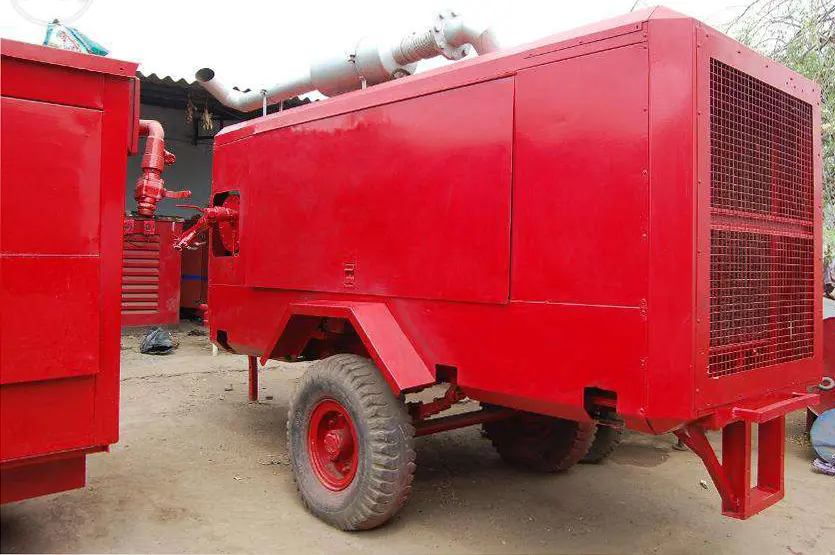
A high-pressure temporary air package must deliver the required mass of air at the pressure, temperature and quality needed by the application. Maximum compressor pressure alone cannot establish suitability. The selected compressor or booster, its feed supply, cooling, treatment, distribution and protective arrangements must operate together across the full duty cycle.
This guide explains how to specify and compare temporary high-pressure air for industrial processes, specialist equipment, drilling and planned or emergency replacement duties. It includes pressure-ratio, capacity and storage examples, supplier response requirements and practical acceptance criteria. Numerical examples are illustrative assumptions, not available-machine ratings or instructions for pressure testing. High-pressure supply from Reddy Compressors requires supplier confirmation and a project-specific engineering assessment.
1 Define high pressure through the application
High pressure is a relative equipment description, not one universal operating band. A requirement above a plant's normal header pressure may be met by a dedicated compressor or a local booster. A specialist application at much higher pressure may require a different machine family, materials, treatment equipment and distribution arrangement. Record actual pressures and units instead of relying on the label.
Begin with the receiving equipment's operating requirements. Identify the minimum pressure while air is flowing, the maximum allowable pressure, the required flow at each operating stage and the permitted temperature and contamination limits. A static gauge reading with the outlet closed does not demonstrate dynamic performance at the process.
Distinguish continuous consumption from charging, intermittent pulses and pressure-holding duties. Continuous users require sustainable compressor delivery. A receiver can support a short peak only if sufficient usable inventory and recharge capacity exist. A charging duty requires an assessment across the changing receiver pressure, not a single advertised flow figure.
Ask whether the whole temporary system needs the highest pressure. Supplying a small high-pressure user from a dedicated branch can avoid raising the pressure of unrelated users. The decision depends on simultaneous demand, installation constraints, control stability and total operating cost; it should not follow a rule that one large high-pressure package is always simpler.
2 Establish the delivery boundary before choosing equipment
The delivery boundary determines what the supplier's performance commitment includes. A pressure and flow promise at the compressor flange differs from a promise at the end of a long temporary hose. Identify the connection by location and tag, then show the treatment, storage, valves and distribution between generation and the critical user.
Record the receiving system's pressure and temperature ratings and its normal operating condition. Identify any lower-rated branch that could become exposed through a valve error, regulator failure or backflow. The system boundary includes these credible interfaces, not just the intended direction of normal airflow.
Separate the required working pressure from the design pressure, maximum allowable pressure, relief setting and any approved test pressure. These values have different purposes. A hire request containing only one number leaves essential engineering decisions unresolved. Do not use an equipment proof-test figure as its permitted continuous operating pressure.
State the gas as well. This page concerns compressed air. A machine advertised for both air and nitrogen still requires confirmation for the selected gas and configuration. Air equipment must never be assumed suitable for oxygen or another gas because the requested pressure is similar.
3 Choose between direct compression and a booster train
A direct high-pressure compressor takes air from the atmosphere and compresses it to the required discharge condition within its designed arrangement. A booster receives air already compressed by another source and raises its pressure further. A booster therefore depends on the availability, pressure stability, quality and temperature of its inlet supply.
Arrangement | Useful application fit | Main dependency |
|---|---|---|
Dedicated compressor | Independent temporary high-pressure duty | Model capacity at required pressure |
Plant air plus booster | Local high-pressure demand with spare plant capacity | Verified spare feed flow and pressure |
Rental feed plus booster | Temporary supply independent of the plant header | Coordinated feed and booster controls |
Parallel complete trains | Capacity or continuity beyond one train | Load sharing and common connections |
Assess the complete train rather than comparing the booster purchase or rental rate alone. Include feed compression, interstage equipment, electrical or engine power, cooling, treatment, drains and final delivery.
Manufacturer booster literature explicitly links inlet pressure and flow with outlet pressure and flow. Use the performance data for the offered model and selected conditions. Do not infer capacity from motor size or transfer a rating from another inlet pressure. [1]
4 Use absolute pressure for compression calculations
Pressure gauges usually indicate pressure above the local atmosphere. Compression ratios use absolute pressure. Write barg for gauge pressure and bara for absolute pressure, and use the local atmospheric pressure when the distinction matters. At an illustrative atmospheric pressure of 1.0 bara, 8 barg corresponds to 9 bara.
Suppose a booster receives air at 8 barg and delivers at 30 barg. With the stated atmospheric assumption, its overall pressure ratio is 31 / 9 = 3.44. Dividing the gauge readings gives 30 / 8 = 3.75, which is not the correct thermodynamic ratio. The error can affect temperature, power and flow reasoning.
If feed pressure falls to 6 barg while outlet pressure remains 30 barg, the ratio becomes 31 / 7 = 4.43. The booster now faces a different duty. Its capacity, absorbed power and temperature behaviour must be checked against the manufacturer's map and limits; they cannot be assumed unchanged merely because the outlet setpoint is unchanged.
For a multistage machine, the overall ratio does not describe the temperature rise in each stage. Interstage pressures, cooling and stage performance matter. The designer's limits govern operation. The ratios above explain why inlet stability is a design input, not permission to alter settings beyond the approved operating envelope.
5 Compare flow at a common reference condition
Free-air delivery, normal volume, standard volume and actual compressed volume are different ways of expressing flow. Record the pressure, temperature and moisture basis associated with each quoted value. A large numerical reduction in actual volume after compression does not mean that most of the air has disappeared.
For a simplified ideal-gas conversion on a consistent dry-air basis, Qline = Qref × (Pref / Pline) × (Tline / Tref). Pressures are absolute and temperatures are kelvin. At higher pressures or where accuracy matters, include gas compressibility and the appropriate moisture correction. Manufacturer-certified performance should take precedence over a rough conversion.
Illustrative example: 1,200 m³/h referenced to 1.0 bara and 20°C is supplied at 31 bara and 40°C. Using 293.15 K and 313.15 K, the ideal estimate is 1,200 × (1 / 31) × (313.15 / 293.15) = approximately 41.4 actual m³/h. The reference flow remains 1,200 m³/h if mass flow is conserved under the assumed dry-air conditions.
This conversion alone does not size a hose or establish a compressor rating. Distribution calculations also require internal diameter, length, fittings, roughness, temperature and allowable pressure loss. At substantial pressure changes, use a suitable compressible-flow calculation rather than treating density as constant through the entire route.
6 Confirm that the feed system has real spare capacity
A plant header pressure that looks stable before connecting a booster does not prove that spare flow exists. Review simultaneous production demand, compressor loading, control response and available reserve over the full operating schedule. A booster may create a new low-pressure supply problem while solving the high-pressure requirement.
Include feed-side treatment and distribution losses when determining pressure at the booster inlet. Measure at the inlet connection during the intended duty. A gauge upstream of a restrictive dryer or undersized hose can overstate the pressure actually available to the booster.
Prepare a mass-flow balance across all branches. Account for dryer regeneration, instrument or seal consumption where applicable, drains, leakage and any feed air used elsewhere. Confirm whether a quoted package flow is gross or already net of these demands. Deducting an allowance twice can oversize the installation; omitting it can leave the process short.
If the feed source also supplies essential plant users, define demand priority. A low-feed-pressure response may require booster unloading or stopping before the plant loses service. That response must be compatible with the high-pressure user's own continuity requirements. The control arrangement should make the trade-off explicit rather than allowing both services to deteriorate unpredictably.
7 Work through a complete capacity balance
Consider an illustrative rental feed compressor delivering 1,500 m³/h at the required feed pressure and site conditions, expressed on one agreed reference basis. Assume a dryer consumes 10% of that gross flow for regeneration. It leaves 1,350 m³/h. A separate low-pressure user takes 100 m³/h, leaving 1,250 m³/h for the booster inlet.
Suppose the booster supplier's data for the selected inlet and outlet conditions indicate 1,100 m³/h delivered at its outlet. This is an assumed map value, not a universal efficiency factor. If high-pressure auxiliary consumption is 40 m³/h, the process receives 1,060 m³/h before any further identified losses.
Against a 1,000 m³/h continuous requirement, the calculated allowance is only 60 m³/h. That allowance must be compared with measurement uncertainty, duty variation and the project's reserve requirement. It is not automatically an adequate design margin, and it does not demonstrate the ability to supply a 1,200 m³/h sustained peak.
Every figure in this balance depends on the stated operating condition. Hotter intake air, a lower feed pressure, increased treatment loss or a different regeneration mode can change the result. Ask the supplier to provide a matching balance for the limiting condition, including the reason that condition controls selection.
8 Address peak demand and receiver recharge
A receiver supplies a temporary deficit by releasing stored air while its pressure falls. Its useful inventory is bounded by the highest permitted operating pressure and the lowest pressure that still serves the process after distribution losses. Physical vessel volume alone does not indicate the available reference-volume inventory.
Using the preceding example, a 1,200 m³/h peak against 1,060 m³/h net supply creates a deficit of 140 m³/h, or 2.333 m³/min. If it lasts 30 seconds, the required inventory is approximately 1.167 m³ on the agreed reference basis.
For a simplified isothermal ideal-gas estimate, available reference volume is Vref = Vvessel × (Pinitial − Pfinal) / Pref × Tref / Tvessel. Assume a usable pressure fall from 31 to 29 bara, Pref of 1 bara and equal vessel and reference temperatures. The calculated vessel volume is 1.167 / 2 = approximately 0.584 m³.
This is an inventory illustration, not a selected receiver. Rapid discharge cooling, real-gas behaviour, outlet losses, control response, rating, inspection requirements and the actual minimum user pressure can require a different design. If normal demand returns to 1,000 m³/h, the available recharge flow is only 60 m³/h, or 1 m³/min. Replacing 1.167 m³ therefore takes at least 1.17 minutes under the simplified constant-surplus assumption. More frequent peaks would progressively deplete storage.
9 Build a pressure budget to the critical user
Start with the minimum pressure required during the controlling flow event, then add justified losses through the actual air path. Use corrected equipment data for filters, dryers, coolers, valves and regulators, including deterioration allowances where appropriate. Keep normal operating variation separate from a blanket unexplained pressure margin.
For example, assume a user needs 25 barg while consuming its specified flow. Treatment loss is estimated at 0.6 bar, hose and manifold loss at 0.8 bar, and a regulating arrangement requires 1.0 bar inlet-to-outlet differential at that flow. The source would need at least 27.4 barg under those assumptions before control variation is resolved.
The regulating differential is an assumed equipment requirement, not a universal value. Obtain the regulator's flow curve and confirm performance at the available inlet pressure. Check both droop under load and downstream pressure when demand closes. A stable upstream gauge is not evidence of a stable regulated outlet.
Confirm that the operating band, control tolerances and foreseeable transients remain compatible with all exposed equipment. If the proposed pressure budget cannot fit within the allowed limits, reduce losses, change the configuration or select suitable equipment. Raising the compressor setpoint without resolving the downstream pressure rating is not an acceptable solution.
10 Treat cooling as part of capacity and reliability
Compression raises air temperature. Intercooling, aftercooling, cooling-air access or cooling-water arrangements must suit the machine and the site. High inlet temperature can affect booster capacity and increase the burden on downstream treatment. Cooling is therefore part of the delivery calculation, not an optional comfort feature.
Check the operating temperature at every material-sensitive interface: compressor outlet, cooler outlet, dryer inlet, filter housing, flexible hose and receiving equipment. A component may have an acceptable nominal pressure rating at one temperature and a different allowable duty at another. Use its documented pressure-temperature limits.
Identify where condensate forms after cooling and how it is separated and drained. A separator that is omitted, overloaded or poorly drained can pass liquid into downstream equipment. Drain devices and condensate handling must themselves be suitable for the pressure and application.
For site deployment, protect cooling paths from recirculation and obstruction. Temporary noise barriers, weather covers and tightly packed rental equipment can change thermal conditions. Record the maximum operating conditions demonstrated during commissioning and investigate sustained temperature trends rather than waiting only for a trip.
11 Preserve the required air quality through boosting
Air quality must be assessed after the complete compression and treatment train. An oil-free feed compressor does not make an oil-lubricated booster oil-free. Conversely, a suitable oil-free booster does not remove contamination already present in its feed or in downstream piping.
State the required particle, water and oil performance at the delivery point, together with any application-specific contaminant requirements. A dryer selected for the feed side and one selected for the high-pressure side have different inlet conditions and mechanical ratings. The location of treatment should follow a coordinated package design.
Review the pressure dew point at the required pressure. Changing pressure changes the relationship between moisture content and condensation conditions. Do not transfer a low-pressure dew-point result to the final high-pressure service without a justified assessment. Verify treatment capacity at the actual temperature, pressure and mass flow.
A label such as instrument quality or clean air does not, by itself, state the complete required performance.
12 Specify the entire pressure containing assembly
Review the ratings and suitability of hoses, rigid piping, manifolds, filters, receivers, drains, valves, adapters, gauges and sample fittings. The lowest applicable limit in an exposed section constrains that section. A high-rated compressor cannot make an unidentified connection suitable.
Connections that physically fit are not necessarily compatible. Confirm thread or flange standards, sealing arrangement, materials, service temperature and pressure rating. Use assemblies prepared and inspected for the duty. Do not base selection on colour, external hose diameter, a supplier's generic description or a proof-pressure marking alone.
Route the system to protect it from vehicles, abrasion, sharp bends, hot surfaces and unintended loading. Support the assembly and accommodate movement in accordance with its design. Any required hose retention or restraint must be selected for the actual assembly; a generic accessory does not substitute for a sound connection.
HSE's pressure-equipment guidance identifies the hazards of pressure-system failure and emphasises equipment suitability, operating limits, protective devices and competent work. It is a useful engineering reference, not a declaration that UK statutory requirements govern an Indian project. The applicable local requirements must be established for the installation. [2]
13 Coordinate regulation and overpressure protection
Normal control and overpressure protection perform different functions. A pressure switch or regulator that manages normal operation should not be assumed to provide all protection required for a lower-rated downstream section. Evaluate credible faults, including a regulator failing open, a blocked outlet and unintended communication between pressure zones.
The package designer should identify protected sections, credible pressure sources, relief arrangements and suitable discharge routing. Protective-device sizing and settings depend on the system and applicable engineering requirements. This article intentionally provides no generic relief setting or test procedure that could be transferred to an unknown installation.
Check what happens when isolation valves are closed. A valve arrangement can leave a trapped pressurised volume or separate equipment from its intended protection. Include maintenance configurations, not only the normal running schematic. Mark isolation and depressurisation points clearly in the operating arrangement.
Plan venting so that noise, discharge forces, contaminants and personnel exposure are addressed. Confirm that the system is isolated and depressurised before opening a connection, using the site's approved procedure. A single gauge reading is not a complete demonstration when separate trapped volumes or blocked instrument connections are possible.
14 Coordinate the feed compressor and booster controls
The control sequence should establish acceptable feed conditions before the booster demands full flow. Define the response to low inlet pressure, excessive temperature, loss of cooling, high discharge pressure and loss of power or fuel. Use the equipment manufacturer's approved controls and protection; do not defeat trips to maintain production.
Review interaction between the feed compressor's pressure band and the booster's demand. A booster that repeatedly loads and unloads can cause header fluctuation, while an unstable feed header can repeatedly interrupt boosting. Storage and sequencing may help, but their settings and volumes need a duty-based assessment.
For multiple machines, document who controls the common pressure and how each unit joins or leaves service. Check start order, minimum run requirements, unloading, non-return functions and restart after a trip. A set of independent rental machines does not automatically behave as one coordinated station.
Place alarms where the responsible operator will receive them and can act. Remote status is useful only if the signal, response responsibility and fallback are established. A communication failure must not remove local protective functions or leave the process team assuming that somebody else has seen the alarm.
15 Keep supply engineering separate from pressure test design
A high-pressure air source may be requested for an approved pneumatic test, but supplying a compressor does not establish that pneumatic testing is the appropriate method. The test owner must determine the method, test medium, pressure, acceptance criteria and personnel protections under the applicable design and site requirements.
Do not infer a test pressure from the rental compressor's maximum pressure. The assembly being tested, its boundaries, stored volume and condition govern the approved test plan. Similarly, connecting a higher-capacity compressor can change the rate of pressurisation and the consequences of a control failure.
For a test-related enquiry, provide the approved requirements to the package supplier and identify responsibility for test controls, instrumentation and isolation. The rental scope should state whether it ends at the supply connection or includes specifically engineered test support. General air hire must not be represented as certification of the tested system.
For drilling or process duties, retain their own specialist operating criteria. Increasing pressure cannot, by itself, solve inadequate flushing flow, an unsuitable tool, excessive distribution loss or a process restriction.
16 Commission against the actual operating envelope
Before operation, reconcile the installed equipment with the agreed schedule and layout. Confirm the actual feed source, booster, treatment, receivers and distribution components. Record substitutions and resolve their impact on capacity, ratings and control behaviour before acceptance.
The commissioning plan should demonstrate the required service at representative normal and peak duties where practicable. Record inlet and discharge pressures, delivered reference flow, relevant temperatures, cooling condition, treatment loss and critical-user pressure. Confirm instrumentation range, measurement basis and calibration status appropriate to the required accuracy.
Check the specified control responses and standby transition using an approved method appropriate to the equipment and site. Do not create an unsafe fault merely to prove a trip. The commissioning authority should define which checks are documentary, simulated or demonstrated under controlled operation.
State limitations honestly. If the installation is commissioned only at part load, record what has and has not been demonstrated. A pressure-hold observation does not establish sustained rated flow. A short successful run does not prove performance at the hottest ambient condition or across repeated storage discharge and recharge cycles.
17 Operate and maintain the complete train
Keep an operating record that connects process demand with the behaviour of the feed and booster stages. Useful trends include feed pressure during loading, final pressure at the critical user, relevant temperatures, treatment differential pressure, drain condition and trip history. Record changes in hose routes, equipment and operating schedule.
Investigate the cause before increasing settings. Falling final pressure may arise from inadequate feed, a changing process demand, a restriction, leakage or reduced machine performance. Rising temperature may involve cooling, pressure ratio, fouling or an operating condition outside the selected map. Measurements should guide the response.
Maintenance support must cover both compression stages and the treatment and distribution equipment. Identify consumables, specialist parts, access, service intervals and who can authorise adjustments. A spare feed compressor does not restore service if the unavailable part belongs to the booster or a high-pressure treatment component.
At demobilisation, use an approved isolation and depressurisation procedure and account for trapped volumes. Protect cleaned connections, record the returned equipment condition and retain operating and acceptance evidence. Temporary status does not remove the need for a controlled end to the installation.
18 Compare quotations with a concise duty schedule
Duty item | Customer information | Supplier confirmation |
|---|---|---|
Process demand | Normal, peak and minimum reference flow | Net delivery at each duty |
Final pressure | Minimum flowing and maximum permitted | Operating band and pressure losses |
Booster inlet | Available pressure, flow and temperature | Required inlet envelope |
Air quality | Limits at the named delivery point | Complete treatment arrangement |
Site conditions | Ambient, altitude, access and cooling | Corrections and deployment needs |
Connections | Layout, route and receiving ratings | Rated component schedule |
Continuity | Tolerable interruption and critical load | Standby and transfer capability |
Acceptance | Required measurements and timing | Demonstration scope and exclusions |
Compare the installed rental cost across the same scope: mobilisation, feed compression, boosting, treatment, hoses, energy, operation, maintenance and return. Clarify which readings determine billable usage and how delays or duty changes are handled. A low booster rate is not meaningful when the necessary feed and cooling package is excluded.
Obtain a written response for deviations. Availability, rated pressure, usable flow and the supplied accessories require project-specific confirmation. Do not treat a historic catalogue range as a promise of current stock, immediate mobilisation or suitability for every application within that range.
19 Questions about temporary high pressure air
Does a booster increase the quantity of air available
A booster raises pressure using an existing feed supply. It does not create additional air mass. Net process flow depends on feed availability, the booster operating map and all consumption or losses across the package.
Can a high pressure compressor run several lower pressure tools
Only through an engineered arrangement compatible with the tools' flow needs and pressure limits. The package must address regulation, overpressure protection and connection ratings. Separate lower-pressure supply may be more suitable than reducing all air from the highest pressure.
Is a receiver enough to cover a larger process demand
It can support a finite peak if usable inventory is sufficient and the system can recharge between events. It cannot cover a persistent deficit indefinitely. Both the pressure floor and the complete demand cycle must be evaluated.
Can an oil free feed compressor preserve oil free final air
Only if the booster and the entire downstream path also meet the required quality specification. Compression technology, treatment, cleanliness and verification must be considered across the complete train.
Why is the same booster rated differently at different inlet pressures
Its mass-flow capability and compression duty depend on inlet conditions and required outlet conditions. Use the supplier's performance map for the actual combination rather than a single headline capacity.
Can equipment be confirmed from pressure alone
No. Provide flow, operating cycle, inlet conditions where relevant, air quality, delivery temperature, site conditions and receiving-system limits. High-pressure package availability and suitability require supplier confirmation.
20 Request a high pressure temporary air proposal
Send the application, required flowing pressure, maximum permitted pressure, normal and peak flow with reference conditions, air quality and operating schedule. Include the rental duration, location, available feed air if a booster is proposed, utilities and the receiving connection details.
Reddy Compressors coordinates project enquiries from Secunderabad and Hyderabad, prioritising Telangana and Andhra Pradesh, with wider project support subject to scope and availability. High-pressure compressors, boosters and specialist accessories are confirmed only after supplier and technical review. Emergency coordination does not imply a guaranteed mobilisation time.
Where drawings or test requirements already exist, provide the relevant approved documents. They allow the proposal to address the real pressure boundary and prevent equipment selection from being based on an incomplete verbal description.
Sources and evidence basis
22 Sources and engineering assumptions
[1] Atlas Copco, Piston Booster Systems, LB air and nitrogen booster range. Manufacturer literature consulted for the dependence of inlet and outlet conditions and model-specific selection. Historical product ratings are not adopted as current rental availability. https://www.atlascopco.com/content/dam/atlas-copco/compressor-technique/industrial-air/documents/brochures/air-compressors/piston-air-compressors/LB%20boosters%20EN.pdf
[2] Health and Safety Executive, Introduction to pressure equipment. Used for general pressure-system risk and operating-limit principles. The UK regulatory context is not asserted as the governing law for the user's installation. https://www.hse.gov.uk/pressure-systems/about.htm
[3] User-supplied B.A. (04-8-26) RC-3 (1).pdf, booster-assisted compression and deep-hole booster engineering sections. Source foundation includes inlet conditions, absolute pressure ratio, cooling, discharge temperature, hose ratings, valves, relief and control coordination. These concepts are adapted to temporary package selection without reproducing the drilling article.
[4] User-supplied Air-Compressors-broucher.pdf, high-pressure diesel compressor section. Used as evidence that a rental package includes application-specific outlets, cooling and accessories. Historical catalogue figures and broad marketing descriptions are not treated as verified purity specifications, current inventory or Reddy Compressors performance commitments.
All numerical examples are illustrative calculations using stated assumptions. They do not select a pressure vessel, set a protective device or prescribe a pressure-test procedure. Final project conclusions about capacity, continuity, energy, air quality or savings must be supported by applicable equipment data and measurements at the agreed operating conditions.