
REDDY COMPRESSORS
From Air Demand to the Point of Use • System Engineering • Lifecycle Performance
QUALITY STATE: Controlled premium draft. Project-specific sizing, pressure, air-quality, electrical, safety, performance and commercial commitments require verification for the actual installation.
Page Control
Field | Controlled value |
|---|---|
Page ID | |
Page title | Compressed Air Engineering Centre |
Page type | Flagship Engineering Hub / System Architecture / Knowledge Gateway |
Primary intent | Connect compressor selection to the complete compressed-air system from demand definition through generation, treatment, storage, distribution, control, point of use, measurement and lifecycle optimisation. |
Audience | Plant owners, engineering and maintenance teams, project managers, procurement teams, consultants and compressed-air users. |
/compressed-air-engineering/ | |
Indexation | INDEX after technical/editorial review |
Schema | CollectionPage + TechArticle + BreadcrumbList + ItemList + FAQPage where eligible |
Primary CTA | Review My Compressed-Air System |
Engineering guidance and enquiry architecture; equipment-specific design and applicable project requirements remain separately verified. |
Compressed air is a system—not a compressor nameplate
A compressor can be correctly selected and the plant can still receive inadequate pressure, unsuitable air quality, unstable control, excessive energy consumption or poor reliability. Useful compressed air is created, treated, stored, distributed, controlled and consumed as one connected system.
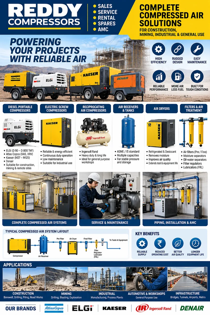
It begins at the work the air must perform and follows the air path backwards to the equipment needed to support it. The objective is not to maximise compressor size. The objective is to define and maintain the required service at the point where the process actually uses the air.
This page is the gateway.
1 — Define the Service at the Point of Use
Begin with the consumer, machine or process. Record required flow, pressure, air quality, continuity, operating pattern and the consequence of falling outside the permitted range. Keep confirmed future loads separate from speculative expansion. A plant-wide compressor selection made before critical consumers are understood reverses the engineering sequence.
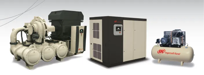
Representative images of machine types we sell, service and rent. Models and capacities are confirmed against your duty.
2 — Build the Demand Profile Before Selecting Capacity
Installed pneumatic equipment does not necessarily operate simultaneously, and nameplate consumption is not automatically the same as measured plant demand. Distinguish base load, normal variation, short peaks, unusual events and future changes. Where measurement is available, retain location, instrument, sampling interval, pressure conditions and operating context. Averaging must not conceal short events that cause unacceptable pressure decay.
3 — Pressure Must Be Budgeted Through the Complete Air Path
Compressor discharge pressure is only the beginning of the pressure path. Treatment equipment, receivers, piping, valves, hoses, filters, regulators and local restrictions can consume pressure before air reaches the user. Define required point-of-use pressure and work upstream through assessed losses. Do not permanently raise compressor pressure merely to conceal poor distribution.
4 — Air Quality Is Defined by the Process
The phrase clean dry air is incomplete unless limits, conditions and measurement boundaries are defined. Aftercoolers, separators, dryers and filters perform different functions. Installing one component does not prove that the complete system meets a process specification. Oil-free compression and application-ready air are separate questions; the complete air path must be considered.
5 — Storage Is a Dynamic System Component
A receiver interacts with demand transients, control behaviour and pressure stability. Its useful effect depends on system pressure limits, demand profile, compressor response and installation location. Receiver sizing should follow the actual engineering objective rather than an unexplained universal litres-per-CFM rule. Applicable pressure-vessel requirements remain project-specific.
6 — Distribution Determines Useful Capacity
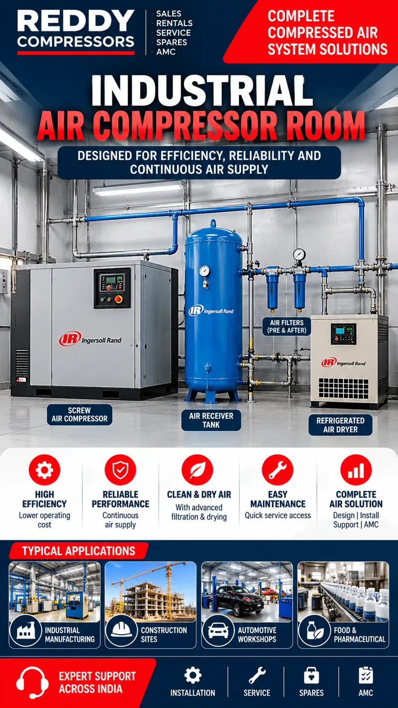
Pipework can make a capable compressor appear inadequate. Undersized mains, restrictive branches, inappropriate fittings, damaged hoses, partially closed valves or poorly maintained treatment can create pressure loss and instability. Review flow, length, diameter, layout, fittings, condensate management and expansion. Your compressor may not be undersized; the distribution system may be preventing capacity from reaching the process.
7 — Controls Should Coordinate the System
Multiple compressors require a control philosophy covering demand, machine ranges, sequencing, pressure bands, unloading behaviour, variable-speed capability, maintenance availability and failure response. Adding a machine without revisiting control can create overlapping bands, unnecessary unloaded running, cycling or unstable interaction. Local controllers, master sequencing and plant automation have different scopes.
8 — Energy Performance Starts With Useful Air
Compressed-air energy analysis should connect electrical input to useful delivered service. A favourable value at one operating point does not establish minimum annual plant cost. Consider demand profile, pressure, control behaviour, unloaded operation where applicable, treatment and distribution losses, leakage, inappropriate uses, cooling requirements and maintenance condition. Measure before claiming savings and verify after implementation.
9 — Reliability Must Be Designed Around Consequence
A workshop tool, automated line and process-critical control function can have different interruption consequences. Define the consequence first, then assess redundancy, isolation, storage, alternative connection, rental contingency, maintenance and spares. Installed spare capacity is not automatically usable redundancy if pressure, quality, connection or control requirements cannot be met.
10 — Instrumentation Turns Assumptions Into Evidence
Pressure, flow, electrical input, dew point where relevant, differential pressure, temperature, machine state and production context can convert a vague complaint into a reviewable operating record. Instrument accuracy, range, installation, calibration and sampling method matter. Data without a trustworthy measurement basis can create a precise but incorrect diagnosis.
11 — Commissioning Must Verify the System Boundary
Commissioning should establish more than whether a compressor starts. The accepted scope determines what must be demonstrated: equipment identity, pressure, capacity evidence, treatment performance, controls, alarms, drainage, distribution behaviour, energy interfaces, documentation and operator handover. Define measurement points, conditions and responsibilities before acceptance.
12 — Maintenance Protects System Performance
Maintenance is not limited to the compressor element. Filters, drains, dryers, coolers, valves, sensors, receivers, distribution and controls can influence system performance. Follow applicable equipment instructions. Retain work records with observations so repeated pressure drop, temperature, moisture, control or energy problems can be recognised as system issues.
13 — Troubleshooting Should Follow Evidence
When users report low pressure, wet air, excessive energy, repeated trips or insufficient capacity, define the symptom and where it occurs. Review upstream and downstream conditions, demand, leakage, restrictions, treatment, controls and exact warning records before replacing equipment. Observation, measurement, diagnosis, corrective action and verification should remain distinct stages.
14 — Expansion Should Preserve the Engineering Basis
New production equipment, shifts, products, pipework or air-quality requirements can invalidate an earlier assessment. Keep the original design basis and update it. Oversizing for undefined growth can increase cost and create poor operating behaviour; ignoring confirmed growth creates early bottlenecks. Separate committed expansion from possible expansion.
15 — Temporary Air Must Meet the Same Requirement
Temporary air for shutdowns, breakdown support or expansion begins with the existing plant specification and connection boundary. Identify flow, pressure, quality, duration, operating pattern, treatment, connection and continuity. A compressor connected upstream of existing treatment is a different scope from a package delivering treated air to the plant header. Availability and mobilisation require confirmation.
16 — Engineering Review Gate
Gate | Required confirmation |
|---|---|
E1 Application | Processes and critical users identified. |
E2 Demand | Flow demand and operating profile documented on a stated basis. |
E3 Pressure | Point-of-use pressure and downstream losses understood. |
E4 Quality | Air-quality limits and verification point defined where applicable. |
E5 Generation | Candidate compressors compared at supported operating points. |
E6 Treatment | Treatment selected for actual inlet/outlet conditions. |
E7 Storage | Storage purpose and transient requirement defined. |
E8 Distribution | Pipework and local connections assessed at relevant flow. |
E9 Controls | Sequencing and pressure-control philosophy documented. |
E10 Energy | Performance evaluated using measured or supported input data. |
E11 Reliability | Continuity strategy reflects interruption consequence. |
E12 Measurement | Instrumentation/data quality supports decisions. |
E13 Acceptance | Commissioning evidence and responsibilities defined. |
E14 Lifecycle | Maintenance, spares, service and future changes addressed. |
17 — What Must Never Claim
A compressor can be selected reliably from motor kW alone.
CFM without pressure and reference basis is a complete duty.
Compressor discharge pressure equals point-of-use pressure.
A fixed capacity margin is correct for every plant.
A larger receiver automatically solves insufficient source capacity.
A ring main is automatically best for every facility.
A VSD automatically saves a fixed percentage of energy.
Oil-free compression alone proves application-ready purity.
Adding another compressor automatically increases usable capacity.
Raising pressure is the preferred remedy for distribution losses.
A maintenance agreement alone guarantees uptime.
A temporary compressor is suitable merely because nominal CFM matches the installed machine.
18 — Frequently Asked Questions
How do I determine compressor capacity for my factory?
Build the demand profile at the required pressure and quality. Use measurements and equipment requirements where available, distinguish simultaneous loads, then compare candidate performance on a compatible basis.
Why can pressure be low when the compressor reaches its setpoint?
The restriction or demand may be downstream. Measure pressure at multiple points during the relevant operating condition and review treatment, piping, valves, hoses, regulators and simultaneous demand.
Should I simply increase compressor pressure?
Not without establishing why point-of-use pressure is inadequate. Higher source pressure can increase energy use and stress while leaving the underlying restriction unresolved.
Will a VSD compressor always save energy?
No universal saving applies. Its value depends on demand profile, operating range, control architecture and the alternatives being compared.
Does oil-free compression mean the air is suitable for every sensitive process?
No. Define the process air-quality requirement and assess the complete air path and verification method.
Can a receiver compensate for an undersized compressor?
Storage can support defined transient requirements, but it does not create sustained compressor capacity. Define the event and system response before sizing storage.
How can I know whether pipework is causing the problem?
Measure pressure at relevant locations under known demand and review the distribution geometry and restrictions. A system pressure profile is more useful than assuming the source is undersized.
Should all installed tool CFM values be added together?
Only when those consumers genuinely operate together in the design case. Establish simultaneity and operating pattern rather than summing every connected nameplate automatically.
Can temporary rental air replace the plant compressor?
It can be assessed for that role. Define the connection boundary, required flow, pressure, quality, treatment, duration and continuity, then confirm suitable equipment and availability.
What should I send for an engineering review?
Process/consumer list, pressure and quality requirements, available flow/pressure/energy data, compressor and treatment details, distribution information, operating schedule, known problems, planned expansion and site constraints.
19 — + Planned Specialist Architecture
Series block | Planned engineering coverage |
|---|---|
Demand profiling, diversity/simultaneity, FAD/reference conditions, capacity and pressure selection. | |
Air Treatment | Aftercooling, separation, dryers, filtration, condensate management and air-quality verification. |
Storage & Distribution | Receivers, headers, ring/branch architecture, pipe sizing, pressure loss, hoses and point-of-use connections. |
Controls & Plant Integration | Sequencing, VSD/fixed-speed interaction, master control, monitoring and plant interfaces. |
Energy & Performance | Measurement, specific energy, leakage, artificial demand, optimisation and verification. |
Reliability & Maintenance | Maintenance architecture, condition monitoring, troubleshooting, overhaul and continuity. |
Industrial Applications | Application-specific air requirements and evidence boundaries. |
Engineering Tools | Calculators, worksheets, audit methods, selection tools and decision records. |
21 — Final Engineering CTA
DO NOT ASK ONLY: “WHAT SIZE COMPRESSOR DO I NEED?”
ASK: “WHAT AIR SERVICE MUST MY PROCESS RECEIVE, AND WHAT COMPLETE SYSTEM WILL DELIVER IT RELIABLY?”
Secondary CTAs: Submit Plant Air Data • Review Compressor Capacity • Review Air Treatment • Review Distribution & Pressure Loss • Review Controls & Energy • Request Rental / Temporary Air • Request Service / Overhaul
Checkpoint Record
Future revisions must be versioned and must not silently replace or shorten this source draft.
V2 STATUS: STAGING READY — TECHNICAL / EDITORIAL VERIFICATION GATED
V2.1 — Engineering Design Basis
A serious compressed-air project begins with a controlled design basis, not a product catalogue. Record processes served, critical users, sustained/peak/low-load cases, minimum point-of-use pressure, air-quality requirement, continuity requirement, schedule, environment, future loads, existing assets and consequences of service failure.
Distinguish facts from assumptions. Measured header flow is evidence of an observed period, not automatically future design demand. Manufacturer consumption is source data, not automatically simultaneous demand. Future production should remain a scenario until committed. Freeze the design basis by revision so later equipment selection and commissioning remain traceable.
V2.2 — System Boundary
Define whether the engineering boundary is package outlet, treatment outlet, receiver, plant header, production block, machine inlet or point of use. Capacity, pressure loss, quality and acceptance change with the boundary.
Map sources, receivers, treatment, headers, interconnections, isolation points, significant consumers and measurement locations. Purge air, drains, leakage, exports and storage effects can sit between a compressor rating and a downstream flow measurement; direct comparison without reconciliation can create a false surplus or shortfall.
V2.3 — Demand as a Time-Dependent Profile
Build normal sustained, peak, low-demand, idle/non-production, critical-service and committed-expansion cases rather than one CFM total. Log flow with pressure and production state where possible.
An average can hide a pressure-critical peak; a maximum can exaggerate continuous duty. A demand-duration curve shows how often flow levels occur, while chronological data shows rapid transitions and repeated events. Use both when the process requires them.
V2.4 — Pressure Architecture
Begin at the process: define minimum acceptable pressure under relevant flow, then work upstream through regulators, hoses, couplings, branches, headers and treatment.
Conceptually, required upstream pressure equals required downstream pressure plus assessed losses plus separately justified control provision. Every term needs a basis. Do not raise the whole plant merely to hide a restrictive hose, filter or branch; locate the loss and correct the architecture where practical.
V2.5 — Airflow Definitions and Reconciliation
Every material flow value needs a data passport: value, units, definition, reference pressure/temperature, humidity basis if relevant, operating pressure, boundary, source and evidence status. FAD, standard/reference flow, actual line volume and displacement are not interchangeable because the units look familiar.
For the same idealised dry-gas mass flow, Q₂ = Q₁ × (p₁/p₂) × (T₂/T₁), using absolute pressure and temperature. This illustrates state conversion; it is not a substitute for the governing compressor rating/test method.
V2.6 — Capacity Architecture
Select sufficient, controllable and maintainable capacity. Oversizing can create unloaded running, cycling or poor turndown; undersizing cannot support sustained demand. Short peaks may be addressed by source response, storage and distribution rather than continuous oversizing.
Separate reserve from redundancy. Reserve is additional capability relative to a design case. Redundancy means the defined service survives an identified outage with pressure, flow, quality and controls still acceptable.
V2.7 — Technology Selection
Evaluate rotary screw, reciprocating, scroll, centrifugal, portable/engine-driven or other architectures against pressure, capacity, load profile, minimum-load behaviour, duty cycle, quality, cooling, utilities, environment, controls, maintenance, overhaul, footprint, noise and expansion.
No family is universally best. VSD is not automatically the efficiency winner; fixed-speed is not automatically obsolete. Family-level descriptions screen options; exact model data closes selection.
V2.8 — Air-Quality Architecture
Define particles, moisture, oil/other contaminants, acceptable condition, pressure/temperature basis, compliance boundary and consequence of deviation. Treatment can include aftercooling, separation, drainage, refrigerated or adsorption drying, particulate/coalescing/adsorption filtration and point-of-use stages.
Avoid under-treatment and blanket over-treatment. Where only selected users require stricter quality, local or segregated treatment can be evaluated. Commissioning must prove quality at the boundary that matters.
V2.9 — Storage Engineering
Receivers store compressed-air mass within a pressure range and influence transient response, cycling and separation. They do not create sustained compressor capacity.
For a peak event, define demand, source contribution, duration and allowable pressure change before calculating storage. Receiver location matters: wet and dry receivers serve different system roles; local storage may help rapid cyclic users. Pressure-vessel requirements remain project-specific.
V2.10 — Distribution Engineering
Useful capacity depends on the network. Internal diameter, length, material, fittings, valves, filters, regulators, hoses, couplings and branch demand influence pressure loss.
Map normal/peak branch flows, measure or calculate losses, identify restrictions and preserve expansion paths. Ring mains are an option, not a universal answer. Always include the final hose/regulator/coupling; the wall header is not necessarily the process boundary.
V2.11 — Controls and Sequencing
Multiple compressors can have enough installed capacity yet operate poorly because of overlapping pressure bands, multiple unloaded machines, unstable trim or cycling.
Define base, trim and standby roles from the demand profile. Coordinate local/master controls to maintain required service while keeping machines within supported ranges. Test representative machine combinations, including maintenance/outage states.
V2.12 — Energy Engineering
Connect electrical input to useful delivered air at required pressure and quality. Log power/energy, flow, pressure, machine state and production context. Motor nameplate power is not annual package energy.
Optimisation should question leakage, inappropriate uses and artificial demand, then pressure, distribution, treatment losses, controls, storage and equipment matching. Savings claims require transparent measurement/modelling and post-change verification.
V2.13 — Reliability and Continuity
Define interruption consequence, acceptable duration, minimum surviving pressure/quality and credible outage cases. Then evaluate standby, isolation, storage, alternate connection, rental contingency, spares and service.
A pre-engineered temporary-air connection can reduce recovery complexity. Define pressure, flow, quality boundary, connection, logistics and acceptance. Availability remains assignment-specific unless contractually committed.
V2.14 — Instrumentation Architecture
A premium plant should explain itself. Consider pressure at source/header/critical branches, flow at system boundaries, package power, treatment differential pressure, dew point where required, temperature and machine state.
Instrument range, accuracy, installation and calibration matter. Synchronise timestamps so pressure events can be compared with flow, controls and production.
V2.15 — Commissioning
Define acceptance boundary, instruments, operating states and pass criteria before testing. Verify equipment identity, cooling/ventilation, drains, pressure control, capacity evidence, treatment, quality where required, receivers/protection, sequencing, alarms, communications, pressure mapping and handover.
If design production load is unavailable, record what was demonstrated and what remains deferred. Partial testing must not become a full-performance claim.
V2.16 — Troubleshooting Architecture
Use symptom → operating condition → measurement → isolation → cause → corrective action → verification. Define where and when the symptom occurs and what changed.
A larger compressor does not fix a blocked filter; a new dryer does not fix a failed drain; higher pressure does not fix a restrictive hose; another compressor can worsen unstable sequencing. Diagnose the system boundary before substitution.
V2.17 — Worked Integrated Example
Illustrative only: a production block has a verified sustained demand of 24 m³/min on a reconciled basis, a recurring 32 m³/min peak lasting 20 seconds, and a critical point-of-use requirement of 6.2 bar(g). Assessed sustained treatment/distribution loss is 0.55 bar. These invented values are not equipment recommendations.
First support the 24 m³/min sustained case at the required upstream pressure. Analyse the 20-second peak separately using source response, system/local storage and allowable pressure decay. Then reconcile dryer/filter capacity at actual inlet conditions, include adsorption purge if applicable, assess low-load controllability, and test the maintenance/outage case. The example shows why capacity, pressure, storage, treatment and controls must be solved together.
V2.18 — Decision Matrix
For every design case, record flow, pressure, quality, duration, criticality, evidence quality and future status. For every candidate architecture, record supported flow-pressure performance, operating range, control method, treatment interface, site applicability, maintenance role, energy evidence and availability.
Keep unresolved items visible. 'Technically plausible pending manufacturer confirmation' is more truthful than a false approval. Keep commercial availability separate from technical fit.
V2.19 — Failure-Mode Review
Review credible failures such as drain failure, dryer trip, rising filter differential pressure, failed flow meter, drifting dew-point sensor, compressor outage, controller bypass, poor ventilation, branch extension or temporary-air connection.
For each material failure define detection, consequence, immediate response, fallback and restoration evidence. This supports operational resilience without replacing formal safety/reliability studies where those are required.
V2.20 — Lifecycle Governance
Retain equipment register, performance data, treatment ratings, pressure map, quality requirements, control philosophy, measurement register, commissioning results, maintenance history and approved modifications.
Production change reopens demand; pipework change reopens pressure loss; lubricant/dryer change reopens treatment and condensate; a new critical process reopens quality and continuity. This keeps the plant engineered over its lifecycle.