
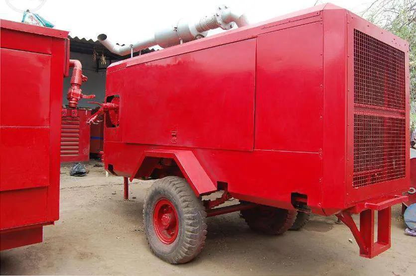
A high-volume temporary air station combines compressors, treatment, storage, controls and distribution to deliver a defined air service at the customer connection. Its usable capacity is the flow that reaches the process at the required pressure and quality under the actual site conditions. Adding compressor nameplate figures does not establish that capacity or prove continuity after a machine fails.
This guide develops a practical method for selecting and operating temporary multi-compressor stations during plant shutdowns, production expansions, seasonal demand and breakdown recovery. It explains demand profiles, net capacity, standby sizing, shared equipment, sequencing, pressure losses and acceptance measurements. Worked scenarios show how apparently generous installed capacity can leave a station short during an outage. All numerical examples are illustrative, not Reddy Compressors fleet ratings or measured project results.
1 Define the station as a complete air service
High volume has no single universal threshold. The relevant question is whether the proposed station can serve the application's simultaneous demand without unacceptable pressure loss, quality deterioration or interruption. A station may consist of several portable machines, electric rental compressors or a combination integrated with the permanent plant.
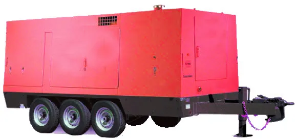
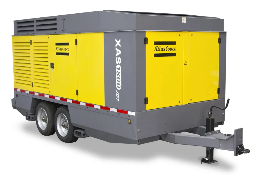
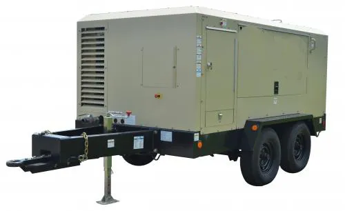
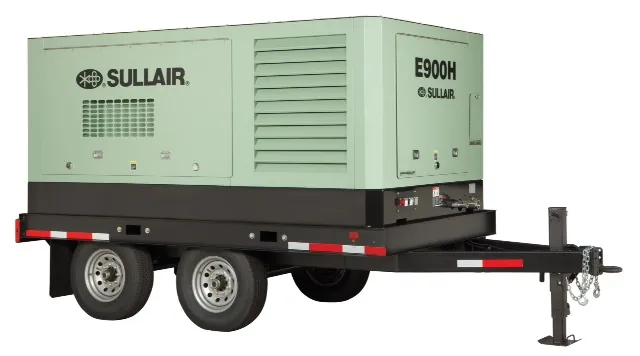
Representative images of machine types we sell, service and rent. Models and capacities are confirmed against your duty.
Specify where delivery is measured. Compressor outlet capacity, flow after a dryer and flow entering the customer's header represent different boundaries. Identify everything included between generation and the named delivery point: coolers, separators, filters, dryers, receivers, manifolds, hoses, valves and meters. Give each major branch a clear purpose.
Separate the station's normal service from its contingency service. Normal service might support every production line, while a defined fault condition supports only essential users. Both can be legitimate designs if the operating team understands the difference. Neither should be described simply as full backup without a stated protected demand.
The station should also have a defined duration and operating calendar. A two-day shutdown with a stable load presents different control, refuelling and maintenance needs from six months of varying production. Duration changes the supporting service even when peak airflow remains the same.
2 Build the demand profile before selecting the fleet
List the users, their required pressure and quality, and their operating patterns. Identify normal production demand, scheduled peaks, short transient events and the minimum overnight or standby demand. Record the evidence behind each value: measurements, equipment data, production schedules or a provisional assumption.

The supplied CFM-selection article distinguishes connected demand from simultaneous, normal, peak and transient demand. Apply that distinction to temporary stations. Ten connected machines do not necessarily demand their maximum air at the same instant; conversely, a planned simultaneous restart can create a peak absent from ordinary production records. [1]
Avoid applying one arbitrary diversity percentage to every user. Understand which processes are linked. Batch valves, cleaning operations and material-handling sequences may be correlated, while unrelated workshop tools may not be. A credible demand profile explains the timing rather than hiding it in a multiplier.
Measure representative operating periods where possible. Include shift changes, start-up, cleaning, weekends and production changes relevant to the rental. Record the sampling interval: an hourly average cannot reveal a twenty-second pressure event. Where evidence is incomplete, retain the uncertainty and decide how it affects capacity allowance and commissioning.
3 Align pressure and flow reference conditions
Every flow figure needs a defined basis. Free-air delivery, normal volume, standard volume and actual line volume are not interchangeable without reference conditions. Record pressure, temperature and moisture basis, and make sure supplier and customer figures describe the same air quantity.
Likewise, capacity must correspond to the intended discharge pressure and site conditions. A compressor rated at one pressure may not deliver the same flow at another. Obtain appropriate performance data and corrections for ambient conditions, altitude where relevant, inlet restrictions and equipment configuration. Do not count a published maximum flow and a separate maximum pressure as a simultaneously available duty.
Distinguish gauge from absolute pressure. Operating setpoints are commonly expressed in barg; gas-law and storage calculations use absolute pressure or a correctly defined pressure difference. State the reference atmospheric pressure in numerical examples where it is needed.
Agree whether meters report flow at reference conditions and whether they measure dry or wet air. Record their usable range and installation requirements. A meter sized only for peak station flow can be unsuitable for accurately observing a small night load, so one instrument may not answer every operating question.
4 Convert installed capacity into net station capacity
Begin with each machine's corrected delivery at the agreed pressure and site conditions. Deduct identified consumption or losses inside the delivery boundary, such as dryer regeneration and station auxiliaries. Check the capacity of treatment and distribution independently: adequate compressors do not make an undersized dryer or manifold larger.
Pressure loss is not a fixed percentage of airflow to subtract. It changes the pressure available at the user and can restrict achievable flow through the system. Model or measure that behaviour separately from actual air consumption. A flow balance and a pressure budget are complementary calculations.
For each operating state, calculate Qnet = sum of available compressor delivery − regeneration consumption − other identified station air consumption. Use a consistent reference basis. If a supplier already quotes net treated delivery, do not subtract the same purge allowance again.
Do not count an unavailable or isolated standby machine as running capacity. Describe installed capacity, running capacity, immediately available reserve and capacity after a defined failure separately. This vocabulary makes a proposal easier to assess and prevents a large total number from disguising a weak operating arrangement.
5 Work through a four machine station example
Assume a temporary station has four identical compressors, each delivering 30 m³/min at the selected pressure and site conditions. Assume each operating treatment train consumes 3 m³/min, leaving 27 m³/min net per complete train. These figures are invented for explanation and all flows share one reference basis.
The required normal production flow is 72 m³/min. A short peak is 90 m³/min. The essential load following an agreed production reduction is 48 m³/min. Three trains can provide 81 m³/min net and cover normal production with a nominal 9 m³/min allowance. Four can provide 108 m³/min and cover the stated peak.
Operating state | Net capacity | Interpretation |
|---|---|---|
Three trains running | 81 m³/min | Covers 72 m³/min normal demand |
Four trains running | 108 m³/min | Covers 90 m³/min peak demand |
One of three trips before standby responds | 54 m³/min | Below normal demand but above essential load |
Three available after one train is lost | 81 m³/min | Covers normal demand but not sustained peak |
The four-train arrangement therefore has a steady-state capacity basis for one-train loss at normal demand, assuming the standby successfully joins and all other equipment remains available. It does not preserve the 90 m³/min peak after one train is lost. It also does not prove an uninterrupted transition during standby starting.
If full peak duty must be sustained after any one complete train is unavailable, this simplified identical-train example requires at least five installed trains: four remaining trains deliver 108 m³/min. Actual selection must still verify control response, treatment, distribution, site services and the chosen capacity allowance.
6 Define reserve and redundancy precisely
Reserve is available capacity above a stated demand. Redundancy describes the ability to tolerate a specified loss. A small reserve margin may absorb load variation without replacing a failed machine. Conversely, an installed spare may provide redundancy after starting but offer no immediate protection during the start delay.
For unequal machines, assess loss of the largest usable contribution and other credible outage states. Subtracting one average machine from installed capacity can overstate the surviving station. Identify whether a failed compressor also removes its dryer, electrical feeder or manifold section.
State the service target in practical terms: normal production after one train is unavailable, essential load during transfer, or full peak with one train isolated for maintenance. These requirements produce different fleet sizes. A generic N+1 label should be accompanied by the actual duty and failure definition.
Distinguish cold standby, ready standby and an already-running reserve arrangement using the supplier's actual capabilities. Starting delay, warm-up, treatment readiness, valve operation and ramp to useful delivery all matter. The station must bridge the demonstrated deficit during the whole transition, not just the time until the engine or motor starts.
7 Evaluate storage against the changing deficit
Storage provides time for controls and machines to respond. The required reference-volume inventory is the integral of demand minus available supply while supply is insufficient. For a constant deficit, the simplified relationship is Vdeficit = Qdeficit × time, using compatible units.
Return to the four-train example. After one of three running trains trips, 54 m³/min remains against 72 m³/min normal demand. If useful standby delivery is unavailable for 20 seconds and the deficit remains constant, storage must provide 18 × 20 / 60 = 6 m³ of reference air. A later ramp-up period would add to that requirement.
For an illustrative isothermal ideal-gas estimate, Vref = Vreceiver × (Phigh − Plow) / Pref × Tref / Treceiver. Assume a usable pressure fall from 8.5 to 7.5 bara, a 1 bara reference pressure and equal reference and receiver temperatures. Supplying 6 m³ of reference air would require 6 m³ physical receiver volume under these simplified assumptions.
This does not select a vessel. The minimum pressure at the user, connecting restrictions, rapid-discharge cooling, instrument response, control tolerances and vessel suitability must be assessed. Existing piping inventory cannot automatically be counted as fully usable storage. Remote volume behind restrictive branches may not release air quickly enough to protect the critical user.
8 Check recharge and repeated events
After the standby joins in the preceding example, three trains again provide 81 m³/min against 72 m³/min demand. The nominal surplus is 9 m³/min. Replacing the 6 m³ inventory takes at least 6 / 9 = 0.667 minutes, or 40 seconds, under a constant-surplus assumption. Actual pressure recovery depends on controls and operating conditions.
For a different event, a 90 m³/min peak against three-train delivery of 81 m³/min creates a 9 m³/min deficit. A thirty-second peak requires 4.5 m³ of reference air. At normal demand, the same 9 m³/min surplus would theoretically recharge that inventory in thirty seconds. This is a complete cycle only if the low-demand interval is actually available.
Repeated events occurring faster than recovery can progressively lower station pressure even though each individual peak looks manageable. Overlapping peaks, standby transitions and dryer switching can make the worst cycle more demanding than a single isolated event. Plot their timing together.
Storage may reduce the number of machines needed for a brief event, but it does not eliminate the energy required to refill it or cover a persistent deficit. Compare storage-based and additional-running-capacity arrangements against the same pressure limits, continuity requirement and total operating cycle.
9 Treat shared equipment as a possible station limit
A station with several compressors may still depend on one dryer, one manifold, one electrical feeder or one controller. The supplied system-design article specifically warns that machine redundancy does not remove common dependencies. Apply its principle to the temporary arrangement as installed, including valves and utility services. [2]
Suppose four compressors can deliver 120 m³/min gross but the common dryer is corrected to only 100 m³/min inlet capacity at the expected temperature and pressure. The dryer is a selection constraint. Do not assume its capacity rises with installed compressor quantity or bypass it to recover flow while retaining the original air-quality claim.
Two parallel treatment units do not automatically share flow equally. Their pressure-drop characteristics, pipe arrangement and isolation state influence the split. Verify both the normal distribution and the duty with one unit isolated. An apparently balanced arrangement can overload the lower-resistance branch.
Build the failure assessment around complete functions: generation, cooling, drying, storage, distribution, control and energy supply. Identify which faults stop the whole station, which reduce capacity and which affect only quality. A running station with unacceptable air quality has lost a required service even if pressure remains healthy.
10 Size headers and temporary distribution for combined flow
The collection header carries the combined flow of the connected running machines. Its duty can be much greater than an individual compressor outlet. Evaluate each section according to the flow it carries, including the configuration with different machines in service and any reverse direction permitted by the arrangement.
Include fittings, couplings, reducers, valves, filters and the final tie-in in the pressure-loss assessment. A generously sized main hose may provide little benefit if a small connection controls the pressure loss. Identify the restriction rather than increasing every machine's pressure in response to a low downstream reading.
Illustrative pressure budget: the critical user needs 6.0 barg. Assume 0.25 bar through treatment, 0.35 bar through the temporary distribution and 0.20 bar through the final connection at the design flow. The source needs at least 6.80 barg before the operating control allowance is resolved. At a higher flow, those losses must be recalculated; they are not fixed station constants.
Check both pressure and temperature suitability of the entire assembly. Establish branch isolation, non-return functions where required, support and protection against site traffic or damage. Avoid accidental exposure of a lower-rated plant section to a higher-pressure temporary source. Detailed hose and manifold design belongs to the distribution plan for the actual installation.
11 Select a control strategy for the full load range
The station should have a clear method for deciding which machines run and which machine follows changes in demand. A base-and-trim arrangement uses suitable machines for relatively steady demand and a selected unit or control method to manage the varying portion. The preferred combination depends on actual part-load performance and continuity needs.
A fixed-speed base machine plus a variable-speed trim machine is one possible arrangement, not a universal answer. Confirm the trim unit's allowable range, minimum flow, pressure capability and compatibility with the other machines. If demand falls below the useful range, the station needs a different operating combination.
Where central control is available, establish the supported interfaces and fallback behaviour. Mixed rental fleets can use different controllers, communication protocols and start permissives. A master-controller proposal must identify the equipment it can actually command and monitor. It must not override local protective functions.
The US Department of Energy sourcebook discusses coordination of multiple compressors, system controls and storage as linked subjects. For a rental station, the practical application is an agreed sequence with demonstrated response, not the assumption that independent pressure switches will organise the fleet efficiently. [3]
12 Avoid unstable sequencing and capacity gaps
Machines controlled independently can repeatedly load together, overshoot and unload together. Excessively separated pressure bands may reduce this interaction at the cost of a wider system-pressure range. Suitable sequencing, storage and pressure sensing should be developed together rather than changing setpoints by trial and error during production.
A capacity gap can arise when the available combinations do not cover demand smoothly. For example, adding a large fixed-speed unit may force the trim compressor below its controllable range. The station then cycles between two unsuitable states. Examine the overlap between running combinations across the demand curve.
Sensor location matters. A controller sensing pressure near one compressor may not represent the common header or critical user during a rapid event. Confirm the intended controlled point, instrument accuracy and response time. Keep local equipment protection independent of remote control availability.
Define minimum run and stop requirements, permitted starting frequency, lead rotation and maintenance substitution using manufacturer limits. Equalising operating hours can support maintenance planning, but should not force an inefficient or unsuitable machine combination merely to make counters match.
13 Integrate the temporary station with permanent plant
When rental equipment supplements an existing station, decide which system controls the common pressure. Identify the intended base supply, trim supply and standby roles. Without coordination, the permanent compressors may unload while rental machines run unnecessarily, or both systems may wait until pressure has already fallen too far.
Verify how the permanent controls interpret pressure during connection and disconnection. Review allowable pressure bands, non-return functions, quality compatibility and possible backfeed. A common connection makes the stations operationally related even when they have different owners or operators.
Use the receiving plant's isolation and changeover procedures. Establish who authorises the transition, who operates the valves and what evidence permits production use. If a temporary station must be ready before a shutdown, complete the feasible pre-connection checks before the permanent plant is taken out of service.
Keep a realistic fallback. Restoring the permanent source is useful only if that source is available and acceptable for the required duty. Otherwise, define the permitted load reduction or controlled production response. A fallback that depends on the failed equipment is not an independent contingency.
14 Design utilities and placement for simultaneous operation
Multiple rental machines need adequate space for cooling, maintenance, refuelling and access. Positioning them closely for convenient piping can cause exhaust exposure, hot-air recirculation or blocked service access. Assess the arrangement with all intended units operating, including the standby when it joins.
For electric machines, assess the supply for running demand, starting events, protection and cable arrangements with qualified electrical personnel. A generator-backed electric station also depends on generator performance during compressor starts and load changes. Do not size the generator from the sum of motor kilowatts alone.
For diesel machines, establish fuel storage, replenishment, access and the consequence of one common delivery failure. Refuelling and maintenance windows should be included in the available-capacity plan. A nominal standby unit may be unavailable during its own service or because the access route is obstructed.
Provide suitable condensate handling and weather protection without compromising ventilation. Review noise at relevant receptors and the site's operating restrictions using applicable requirements. The station layout should show occupied areas, traffic routes and service clearances, rather than only the compressor footprints.
15 Compare energy and hire cost at station level
Evaluate the operating combination across the demand profile. A station can have efficient individual compressors but waste energy through unloaded running, excessive pressure, poor sequencing or avoidable treatment losses. Include auxiliaries and the chosen measurement boundary when comparing alternatives.
For illustration, suppose Arrangement A consumes 420 kW while serving the defined duty, and Arrangement B consumes 390 kW with equivalent measured flow, pressure and quality. Over an assumed twelve-hour operating day, the difference is 30 × 12 = 360 kWh. At an assumed marginal energy cost of ₹9/kWh, that is ₹3,240 per operating day, not a current tariff or guaranteed saving.
If Arrangement B costs ₹2,000 more per operating day in hire and support, the illustrative net advantage is ₹1,240 per day before mobilisation differences and other costs. Over thirty operating days it becomes ₹37,200. This comparison is valid only if the assumed performance persists across the relevant operating states.
For a diesel station, use fuel measured over comparable duty rather than equating litres per hour with efficiency independently of output. Record unloaded hours, replenishment, maintenance and operator costs. Exclude claimed savings, avoided downtime or recovered production from project conclusions unless the evidence supports them.
16 Measure the station and its useful output
At minimum, establish a measurement arrangement that can connect delivered service to machine behaviour. Relevant records include common-header and critical-user pressure, net delivered flow, machine loading or speed, treatment condition and electricity or fuel consumption. Synchronise timestamps so a pressure event can be related to its cause.
Choose measurement locations that answer the question. Compressor outlet flow may establish machine contribution, while a meter after the treatment and station auxiliaries establishes a different delivery boundary. A customer-header meter may include temporary and permanent sources together. Label the data accordingly.
For air-quality requirements, measure the relevant parameters at the agreed location under representative operation. Pressure and flow instruments cannot establish particle or oil performance. Conversely, a satisfactory quality sample does not prove peak capacity or standby response.
Preserve as-found and as-left records after adjustments. If a control change improves pressure stability, retain the load and production context rather than presenting a single favourable graph. The customer's operational decision should be based on comparable evidence with any limitations stated.
17 Commission the station across meaningful states
Prepare a commissioning schedule covering the service states that control the design. These commonly include normal demand, minimum demand, the agreed peak, machine staging, planned isolation and restoration after a specified failure. Use approved methods appropriate to the site; do not manufacture an unsafe fault to obtain a demonstration.
Demonstration | Evidence to record | Acceptance question |
|---|---|---|
Normal production | Flow, pressure and running combination | Is required net service sustained |
Minimum demand | Control state and cycling behaviour | Can the station operate stably |
Peak event | Duration and critical-user pressure | Is the event served or buffered |
Standby transition | Deficit, response time and recovery | Is interruption within the agreed limit |
Treatment isolation | Surviving capacity and quality | Does the contingency duty remain valid |
Return to service | Staging and storage recharge | Is the next event supportable |
Document the configuration used in every demonstration. A trial with all machines running does not establish performance with a designated standby stopped. A short run with a clean dryer does not resolve the pressure budget for the permitted service condition without further evidence.
Where full production demand cannot be reproduced, identify which requirements were demonstrated and which remain supported by calculations or supplier data. Do not turn a partial test into a full-capacity acceptance statement. Agree the follow-up observation when the relevant production condition occurs.
18 Operate with clear responsibilities
Assign responsibility for the complete station, including the interfaces between rental supplier, site engineering, production and quality teams. Operators should know who can alter setpoints, start an additional unit, isolate a branch or authorise a change to the protected demand.
A shift record should note running machines, available standby, pressure trends, treatment alarms, fuel or electrical issues, maintenance and changes in production. State when a machine is unavailable even if it remains physically on site. Capacity planning should follow operational status, not equipment count.
If pressure falls, compare source and user readings before assuming that another compressor is required. High station pressure with low remote pressure suggests a different investigation from low pressure throughout the system. Review simultaneous demand, restrictions, leakage, treatment loss and control response using the evidence available.
When the rental ends, plan the return to permanent supply, confirm its readiness and follow the agreed isolation and depressurisation procedure. Retain the final equipment configuration and operating records. The handover should leave the plant team clear about which temporary settings or connections have been removed or restored.
19 Questions about high volume temporary stations
Can compressor capacities simply be added together
Only after matching pressure, reference conditions and site corrections. Net delivery must also account for station air consumption and the limits of treatment and distribution. Installed totals alone do not prove useful process capacity.
Does one spare compressor guarantee uninterrupted air
No. Its start and loading response must be compatible with the demand and available storage. Shared treatment, power, fuel, control or header failures can also defeat the intended redundancy.
Should every rental machine have variable speed control
Not necessarily. Select the running combinations from the demand profile and available performance data. Suitable base machines with one controllable trim arrangement may be effective, while other duties need a different architecture.
Can a larger receiver replace an additional compressor
It may cover a finite peak or transition if pressure limits and recharge time allow. It cannot supply a sustained capacity deficit. Evaluate the complete cycle and the actual rate at which usable air can leave storage.
Can rental compressors operate with the permanent station
Yes, where pressure control, flow sharing, quality, protection and connection arrangements are compatible. Agree roles and changeover responsibilities so the two stations do not work against each other.
What information is needed for a proposal
Provide normal, peak and minimum demand; flow reference conditions; pressure and quality requirements; operating hours; duration; site utilities; connection details; and the required service after a failure. Include measurements and production schedules where available.
20 Arrange a temporary station assessment
Reddy Compressors supports temporary-air enquiries from its Secunderabad and Hyderabad base, prioritising Telangana and Andhra Pradesh, with wider project support subject to scope and availability. Proposed machine quantities, treatment, controls and mobilisation arrangements require project-specific confirmation.
Send the existing demand profile, station diagram, planned shutdown or production schedule and the receiving connection details. Identify the critical load and the acceptable interruption during transfer. These inputs allow the proposal to distinguish normal capacity from standby capacity and to include the equipment that turns multiple compressors into a functioning station.
Emergency coordination does not imply a guaranteed response time or immediate availability of a complete multi-machine package. The enquiry response should identify what can be provided, what depends on supplier confirmation and the evidence needed for the agreed delivery duty.
Calculators and worked examples
These tools give indicative figures for screening, comparison and for preparing an enquiry. They run in your browser and send nothing. Prices, tariffs and efficiencies shown are example values: replace them with your own. Results are not a performance guarantee or a design certificate; final selection is confirmed by an engineer against the machine data sheet and the site.
Compressed air demand estimate
Add up the air your tools and processes use, apply duty and simultaneity, then add leakage and growth allowances to reach a capacity to enquire about.
The worked example below shows the method with fixed numbers. Turn on JavaScript to change the inputs.
Worked example
Inputs
- Group A: number of tools: 6
- Group A: free air each (L/s): 4
- Group A: duty (%): 40
- Group B: number of tools: 2
- Group B: free air each (L/s): 15
- Group B: duty (%): 60
- Group C: number of tools: 1
- Group C: free air each (L/s): 40
- Group C: duty (%): 80
- Simultaneity of all tools (%): 65
- Leakage allowance (%): 15
- Growth allowance (%): 10
Result
- Connected demand: 94 L/s
- Average demand (duty-weighted): 59.6 L/s
- Simultaneous peak: 61.1 L/s
- Design capacity with allowances: 77.29 L/s = 4.64 m³/min = 163.8 CFM
Method. Average demand = Σ(number × air per tool × duty). Peak = Σ(number × air per tool) × simultaneity. Design capacity = peak × (1 + leakage) × (1 + growth).
What to take from it. Leakage and growth allowances move the answer as much as any single tool. Where you can, replace catalogue figures with measured ones.
Sources and evidence basis
22 Sources and calculation boundaries
[1] User-supplied B.A. (13-8-26) RC-1.pdf, CFM-selection and demand-profile sections. Used for the distinction between connected, simultaneous, normal, peak and transient demand, and the need to associate airflow with pressure.
[2] User-supplied B.A. (16-8-26) RC-2.pdf, system selection, variable demand, sequencing and reliability sections. Used for base-and-trim alternatives and common dependencies involving power, cooling, drying, controls and headers. Station examples here are newly developed illustrations rather than recovered project measurements.
[3] US Department of Energy, Improving Compressed Air System Performance — A Sourcebook for Industry, system controls and storage discussion. Used for general coordination principles; no published savings percentage is adopted as a rental-station guarantee. https://www.energy.gov/sites/default/files/2014/05/f16/compressed_air_sourcebook.pdf
All calculations use stated illustrative assumptions. Storage examples use a simplified isothermal ideal-gas model and do not select or certify pressure vessels. Machine performance, treatment corrections, control timing and utility capacity require confirmation for the actual equipment. Project conclusions about output, continuity, quality and savings must follow appropriate measurements and documented operating conditions.