
Reddy Compressors
Construction air supply must follow the work front. A compressor that supports two crews beside an access road may fail to deliver adequate tool pressure after those crews move behind a building, extend their hoses and begin working simultaneously. The useful specification is therefore the air delivered to each active work zone, at the required operating pressure and quality, through the distribution arrangement that will actually be installed.
This guide explains how project engineers, contractors and site supervisors can plan temporary compressed air for changing construction activities. It covers tool schedules, simultaneous demand, central and distributed packages, pressure loss, moisture, access, relocation, shift control and cost per completed task. Numerical examples are hypothetical engineering illustrations, not equipment selections, quotations or claims about a completed Reddy Compressors project.
01 Define the construction work zone
A work zone is an identifiable area with a defined activity, responsible supervisor, air connection and period of use. It may be a demolition bay, bridge deck, pipeline trench, fabrication area or building floor. Its boundary should be clear enough that the air supply can be isolated, inspected and handed over without confusion with an adjacent contractor’s equipment.

The zone description must include what changes during the job. A fixed workshop with predictable shifts differs from a crew advancing along a trench. Work at height requires a distribution route and support arrangement suited to that route. Excavations and enclosed areas introduce access and ventilation constraints that cannot be solved simply by purchasing a larger compressor.
Separate ordinary pneumatic-tool duty from specialist applications. Instrument air, breathing air, pressure testing, tunnelling systems and high-pressure drilling require their own specifications. Their proximity to a construction work zone does not make ordinary tool air suitable for them.
02 Build an activity and tool register
Record each tool’s manufacturer, model, quantity, required inlet pressure, rated consumption and stated consumption basis. Identify whether the published figure represents continuous running, an averaged working cycle or a particular operating condition. A generic description such as “four breakers” cannot establish demand because different tool sizes and operating modes consume different amounts of air.
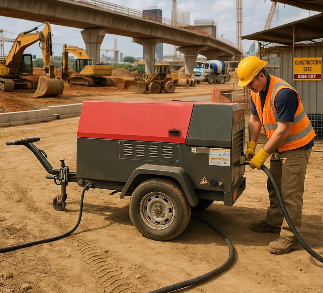
Record the required hose diameter, permitted length or other manufacturer limitations, connection type and lubrication instructions. Note whether accessories consume additional air. Include pumps, vibrators, blowdown devices and intermittent cleaning equipment only where they are authorised for the task. Unrecorded small consumers can collectively become a material load.
Tool availability is different from tool simultaneity. Ten tools in the store may support three active operators, while four crews starting together may require nearly their full connected load. Build the register around the programme and crew deployment. Preserve the source of each consumption value so a later model substitution can be assessed promptly.
03 Establish operating scenarios instead of one average
Define normal work, credible overlap, start of shift, restart after interruption and the next planned work phase. For each scenario, identify which tools can operate together and which must remain available if a compressor stops. A daily average is useful for energy estimates but can conceal the interval that determines compressor capacity and distribution performance.
The following figures illustrate a three-zone schedule. They are assumed reference-air flows on a common basis, not manufacturer ratings. Actual tool schedules must replace them before procurement.
Zone | Assumed equipment and flow | Scheduling constraint |
|---|---|---|
A demolition bay | Two tools at 1.8 m³/min each giving 3.6 m³/min | Both operate during the main shift |
B surface preparation | Three tools at 0.9 m³/min each giving 2.7 m³/min | Shares access with inspection work |
C drilling area | Two tools at 1.4 m³/min each giving 2.8 m³/min | May overlap with Zones A and B |
Common auxiliaries | 0.4 m³/min measured or justified allowance | Included whenever the station operates |
All three zones operating together require 3.6 + 2.7 + 2.8 + 0.4 = 9.5 m³/min. If a controlled programme prevents Zone C from overlapping with Zone B, the largest listed combination is A plus C plus auxiliaries, or 6.8 m³/min. That reduction depends on enforceable coordination. It is not justified by applying an arbitrary diversity percentage to every tool.
04 Convert the schedule into net delivered capacity
Specify compressor output at the required operating pressure and relevant site conditions. Keep free-air delivery, standardised volume and actual compressed volume distinct. Values can be combined only after their reference bases are reconciled. A displacement figure or an airflow rating at a lower pressure is not automatically the usable supply for the scheduled tools.
Where treatment consumes air, distinguish gross compressor output from net delivered flow. For the 9.5 m³/min example, an assumed treatment purge equal to 8% of gross flow requires 9.5 ÷ 0.92 = 10.33 m³/min gross, before any further justified allowances. A package delivering 10 m³/min gross would supply only 9.2 m³/min under that assumption and would be short by 0.3 m³/min during full overlap.
The purge figure is illustrative; many tool-air arrangements do not use such a dryer. Apply losses only to the actual equipment train. Check ambient and altitude corrections from the supplier, treatment capacity, hose losses and acceptable control margin. Avoid adding several unexplained percentages that inflate the selection without clarifying what uncertainty each allowance covers.
05 Select central or distributed supply
A central station can consolidate servicing, fuel access and supervision. It may suit several nearby zones with compatible pressure and quality requirements. Its main distribution must carry the simultaneous flow, and the project must manage the consequence of a common failure. One damaged main line or blocked access point can affect every connected crew.
Distributed compressors can shorten hoses and allow an advancing crew to relocate independently. They also multiply inspection points, fuelling tasks, noise sources and service requirements. Small units operating lightly loaded may be less attractive than expected when evaluated over a full shift. Compare the operating behaviour of the actual packages rather than assuming either arrangement is always more efficient.
Arrangement | Strong reason to consider it | Main constraint to resolve |
|---|---|---|
One central station | Nearby zones with coordinated demand | Main line capacity and common failure exposure |
Separate zone packages | Distant or independently moving crews | Multiple service locations and local access |
Central base with local supplement | A remote or short-duration high-demand task | Clear pressure control and connection boundaries |
Standby or replacement package | High consequence of air interruption | Connection readiness and realistic restoration time |
Treat mixed arrangements as designed systems. A second compressor connected casually to a common header can introduce backflow or control interactions. Confirm permitted parallel operation, isolation, non-return arrangements and pressure ratings before making the connection.
06 Calculate pressure at the working tool
The tool needs its specified pressure while consuming air. A gauge reading at the compressor during no-flow conditions does not prove that pressure will remain adequate at the farthest tool. Measure or calculate the loss through treatment, the main supply, manifold, branch hose, couplings, regulator and any lubricator within the defined boundary.
For illustration, a tool requires 6.0 barg at its inlet. Estimated losses at the relevant simultaneous flow are 0.20 bar through treatment, 0.35 bar in the main route, 0.25 bar through the manifold and branch, and 0.15 bar through local accessories. The upstream pressure requirement is therefore 6.95 barg before allowing for the actual control band and operating variation.
This calculation does not authorise a 6.95 barg setting on any available machine. Verify the whole system’s allowable pressure and the tool’s maximum inlet pressure, including low-flow periods. A regulator may be needed to protect lower-pressure users. Raising station pressure to overcome a restricted coupling can increase consumption elsewhere while leaving the underlying distribution defect unresolved.
07 Make distribution suitable for movement and traffic
A construction distribution route must work physically as well as hydraulically. Mark crossings, lifting routes, access roads, emergency routes, excavation edges and areas where hot work or sharp debris could damage hoses. Select protection and support appropriate to the hose, vehicle loading and site layout. Do not leave the hose itself to carry mechanical loads it was not designed to withstand.
Use the actual internal diameter and the restrictions of fittings in pressure-loss calculations. Several small couplings can dominate the performance of a nominally large hose. Check the manufacturer’s pressure and temperature ratings for the entire assembly, including couplings, clamps and accessories. The allowable duty is limited by the weakest relevant component.
Long runs should prompt a comparison of a larger main with short tool branches, a relocated compressor or separate local supply. Do not assume that each additional extension merely increases the same small pressure drop. Loss changes with flow and pressure, and simultaneous crew operation can expose restrictions that were invisible during an individual-tool trial.
08 Control hose failure and stored pressure
Compressed-air hoses contain stored energy. The site arrangement must address accidental disconnection, damaged assemblies, uncontrolled tool attachments and residual pressure during intervention. Use compatible positive connections, tool retainers and hose-failure protection as required by the equipment manufacturer and applicable site rules. A restraint and an automatic flow-limiting device perform different functions; one should not be assumed to replace the other.
The United States OSHA construction tool standard, 1926.302, is a useful international reference for positive hose connections, tool retainers, equipment pressure limits and source-side hose-failure protection. It is cited here as a technical reference, not as a declaration of the legal requirements for an Indian project. The contractor must establish the rules applicable to the site and equipment.
Plan isolation and verified pressure release before disconnecting, repairing or relocating an assembly. A non-return valve can trap pressure downstream. The site-specific method must identify all energy sources and trapped sections. Never lift or lower a tool by its air hose. Remove damaged assemblies from use rather than relying on improvised repairs or additional tightening under pressure.
09 Match moisture control and lubrication to the task
Hot compressor discharge can cool inside long outdoor hoses and produce condensate. A separator near the compressor may remove liquid already present there while further liquid forms downstream. Identify cooling points, low sections and the moisture tolerance of each tool or process. Select aftercooling, separation, drainage and drying according to the actual condition required at the user.
Tool lubrication must follow the tool manufacturer’s instructions. Where lubrication is required, locate and adjust the device for the intended branch. Avoid distributing lubricated air into a shared main serving activities that require clean air. A coating or adhesive process can be sensitive to contamination that an impact tool tolerates; sharing one compressor does not eliminate this difference.
Keep drainage accessible and manage condensate through the site’s approved arrangement. Water mixed with compressor lubricant is not simply clean rainwater. Check drainage during representative operation, particularly after cooler nights, rain or a route change. Compressor type alone does not establish final air quality, and tool air must not be presented as breathing air.
10 Coordinate placement with the site logistics plan
Locate the package where it can be operated and serviced without blocking access, emergency response or construction movements. Confirm ground bearing suitability, stability, clearances, access for lifting or towing, and the manufacturer’s permitted operating orientation. A location that appears convenient on the first day may become inaccessible after scaffolding, shuttering or material storage is installed.
For engine-driven equipment, assess exhaust movement relative to workers, occupied spaces and air intakes. Do not place it in an enclosed or poorly ventilated location on the assumption that opening a door provides adequate ventilation. Enclosed-area work requires a specific assessment of ventilation, exhaust and other site hazards, including applicable confined-space controls where relevant.
For electric equipment, verify the supply and protection through the responsible electrical team. Account for cable routing, voltage conditions, starting behaviour, isolation and exposure to site damage. Compare diesel and electric options using the available infrastructure and duty profile. Availability of a socket or a nearby generator does not prove that the proposed electric compressor can be supported.
11 Treat relocation as a change in the engineered system
Moving a work front changes more than hose length. It may alter elevation, exposure, access, communication, demand overlap and the location of drainage points. Define the point at which the existing arrangement must be reassessed, such as a new floor, a road crossing, an additional crew or an extension beyond the approved route.
Suppose the original route has a verified 0.35 bar main-line loss at the scheduled flow. A revised route produces 0.80 bar under the new conditions. With the original station setting unchanged, the additional 0.45 bar loss reduces pressure available to the tool. The response may be a better route, larger main or local package; it should not automatically be a higher pressure setting.
Before a move, identify who isolates and releases pressure, who authorises lifting or towing, who reconnects the assembly and who proves the revised duty. After the move, inspect connections and demonstrate representative simultaneous operation. Mark superseded routes and remove redundant hoses so later crews do not reconnect to an obsolete arrangement.
12 Use scheduling as a documented capacity measure
Scheduling can reduce the largest overlapping demand when the work programme permits it. Returning to the example, preventing Zones B and C from operating together reduces the listed peak from 9.5 to 6.8 m³/min. This may support a smaller package or improve pressure stability, but only if the programme impact and labour consequences are acceptable.
Give the arrangement a named supervisor, communication method and rule for exceptions. Record whether waiting time is planned or accidental. A smaller compressor that saves hire cost but forces an expensive crew to wait may increase the project’s total cost. If a subcontractor can bypass the schedule without notice, the lower demand is not a dependable sizing basis.
Separate a genuine scheduling constraint from an assumption that operators will seldom press their triggers together. Common break times, concrete deliveries and restart after a stoppage can synchronise otherwise intermittent loads. Check the schedule against a plausible busy interval, then verify it during site operation before treating it as a repeatable operating method.
13 Use storage only for an identified transient
A receiver can support a brief difference between demand and compressor delivery, provided its usable pressure range and refill opportunity are adequate. It cannot supply a persistent deficit indefinitely. Express both demand and delivery on the same reference-air basis before estimating stored-air support.
For an illustrative 1.2 m³/min shortfall lasting 15 seconds, the missing reference volume is 1.2 × 15 ÷ 60 = 0.30 m³. Under an ideal-gas, equal-temperature approximation with a 1 bara reference and usable receiver pressure falling from 8 bara to 7 bara, the receiver volume corresponding to that quantity is 0.30 × 1 ÷ (8 − 7) = 0.30 m³. Pressure values in this relationship are absolute.
This is a volume balance, not a final receiver selection. Downstream pressure losses, minimum tool pressure, discharge rate, temperature response, control behaviour and pressure-vessel requirements still apply. At a genuine recharge surplus of 0.6 m³/min, replacing 0.30 m³ takes at least 30 seconds on this simplified basis. Repeated bursts with less recovery time progressively exhaust the reserve.
14 Plan continuity around the consequence of interruption
Define what happens when air stops. A crew may be able to pause safely, or an interruption may disrupt a time-sensitive sequence involving other equipment and subcontractors. Distinguish the ability to finish a critical step from the ability to maintain all tools at full output. This distinction helps size contingency without claiming universal standby protection.
Two compressors do not necessarily provide redundancy. If each contributes 5 m³/min net to a 9.5 m³/min duty, losing one leaves a 4.5 m³/min deficit. The remaining unit may support a reduced set of zones, but it cannot maintain the original schedule. Document which activities stop and who communicates that change.
Check shared dependencies such as a common manifold, one electrical source, one fuel access route or one vulnerable distribution crossing. A standby machine still requires placement, compatible connections and verification. Restoration time should reflect those tasks and the actual support arrangement; it must not be described as immediate merely because a spare machine exists elsewhere.
15 Commission with the crews that will use the air
Commissioning should demonstrate the defined service at the work zones. Confirm equipment identities, pressure ratings, approved hose routes, isolation, protection, drainage, tool compatibility and relevant inspection records. Establish who can start, stop, adjust or extend the system. Use the site’s approved method for controlled energisation and checks.
Run a representative simultaneous-tool trial. Record compressor pressure, manifold pressure and pressure at the limiting tool inlet while it operates. Record which tools are active, the hose configuration and any treatment state that affects available flow. A test with only one tool cannot demonstrate a three-zone peak. Assess tool performance and relevant air quality alongside the gauge readings.
If pressure falls, locate where it falls. Stable compressor pressure with a large branch drop points toward distribution or local restrictions. Falling station pressure during sustained full loading suggests a supply-demand imbalance or another station limitation. Check measured evidence before changing pressure or adding machinery. Retain the accepted configuration as the reference for subsequent moves.
16 Make each shift handover operationally useful
The handover should state the active zones, approved tool combinations, pressure setting, fuel or electrical status, drainage condition and unresolved defects. Include planned moves, additional contractors and restrictions introduced by other site activities. A short current record is more useful than a long generic checklist that no longer matches the work front.
Inspect for damage and leakage using an approved method. Check that hose protection has not been displaced by traffic and that isolation points remain accessible. Investigate unusual heat, vibration, control behaviour or tool performance through competent personnel and the equipment instructions. Stop and isolate unsafe equipment according to the site procedure.
Track compressor running hours separately from productive tool hours. During long pauses, apply an approved shutdown or standby strategy that respects restart requirements and site continuity. An engine running throughout an entire shift does not mean every hour contributed useful work. Equally, automatic shutdown should not surprise crews that rely on an agreed supply window.
17 Compare cost per accepted construction output
Evaluate total support cost against an output that the contractor accepts: metres drilled, area prepared, quantity broken out or another measurable task. Include hire, mobilisation, fuel or electricity, distribution, operator arrangements, servicing and relevant waiting time. Keep rework and quality acceptance visible so faster but unacceptable work is not presented as better performance.
For illustration, Package A costs ₹18,000 per shift in total and supports 72 accepted task units, giving ₹250 per unit. Package B costs ₹22,000 and supports 100 accepted units, giving ₹220 per unit. Package B is cheaper per accepted unit in that scenario despite its higher shift cost. If its actual output is only 80 units, its cost becomes ₹275 per unit and the conclusion reverses.
Use comparable materials, crew capability, access and task definitions before attributing the difference to compressed air. A hard rock layer or restricted working window can dominate productivity. Measure the trial, state its conditions and separate observed results from forecasts. Neither a larger compressor nor a higher pressure setting guarantees faster construction output.
18 Separate site time from operating time
Hire duration often includes mobilisation, access delays, standby, operating shifts and demobilisation. Energy use depends on operating states rather than the total calendar duration alone. Prepare a duration schedule that identifies the planned start, likely changes, minimum commitments and extension arrangements before comparing offers.
Assume a diesel package operates for six hours at an illustrative 18 L/h and two hours at 7 L/h during a shift. Consumption is 6 × 18 + 2 × 7 = 122 litres. Multiplying the higher rate by eight hours would give 144 litres and overstate this assumed profile; multiplying only productive hours would omit the remaining 14 litres. Use measured or supplier-supported state data for an actual forecast.
Refuelling access must fit the work programme and equipment instructions. The fuel plan should include usable capacity, consumption uncertainty, supply access and a safe servicing window. An electric option needs equivalent attention to supply interruptions and distribution constraints. Compare full installed arrangements, including a generator when grid power is unavailable, rather than comparing fuel with electricity in isolation.
19 Prepare a clear enquiry and scope of supply
Send the project location, dates, shift pattern, work-zone plan, tool register, simultaneous scenarios, required inlet pressure and relevant quality needs. Include the farthest and most restricted routes, access limitations, likely relocations and consequence of interrupted air. Photographs and a marked site plan can resolve ambiguities that a compressor-capacity request leaves open.
Ask the quotation to define the delivery boundary. Identify who supplies the compressor, treatment, main hoses, manifolds, branch hoses, local accessories, protection, fuel or electrical connection, operator support and movement equipment. Confirm what is included for extensions, additional tools, after-hours work and return-condition requirements. A clear boundary makes competing offers meaningfully comparable.
For Reddy Compressors enquiries, describe the site in Hyderabad, Secunderabad, Telangana, Andhra Pradesh or the relevant project location. Equipment configuration, wider project support and mobilisation arrangements require confirmation against the duty and site. Submit the tool schedule and work-front plan for a project-specific proposal rather than relying on an unverified universal package size or response-time promise.
20 Frequently asked questions
How many tools can one rental compressor operate
The answer depends on each tool’s consumption at its required pressure, simultaneous operation and net capacity delivered through the installed system. Add the relevant tool flows on a compatible reference basis, include actual auxiliaries and treatment consumption, and check pressure at the limiting tool. A compressor’s nominal CFM label alone cannot establish a dependable tool count.
Can one compressor supply several construction floors
It can be considered where capacity, pressure, hose or piping design, support, isolation and access are suitable. Evaluate the actual route and each floor’s simultaneous demand. Provide identifiable zones and a controlled method for adding or moving connections. The final arrangement must also satisfy the site’s lifting, fire access, traffic and work-at-height requirements.
Why does a tool lose power when another crew starts
The additional crew may exceed net supply or increase pressure loss through a shared main, manifold or coupling. Record pressure at the station and affected branch during the event. Also check local regulation, filtration, tool condition and leakage. Those observations help distinguish a capacity shortfall from a distribution restriction before equipment is changed.
Does every construction tool require a dryer
No universal treatment train fits every tool. Determine moisture tolerance, ambient conditions, hose cooling and the manufacturer’s requirements. Some tasks need separation and reliable drainage; others need a specified dew point or tighter contamination control. Select treatment for the actual duty and account for its pressure loss and any purge consumption in the supply calculation.
Can existing hoses be reused after the work front moves
Only after their condition, ratings, compatibility and new routing are checked. The previous arrangement’s acceptable pressure does not prove the longer route will perform adequately. Reassess protection, supports, drainage and access, then verify the revised configuration under representative load. Damaged or unsuitable assemblies should be removed rather than incorporated because they are already on site.
Is the lowest daily rental price the cheapest option
Not necessarily. Compare the total installed cost, operating energy, crew waiting, accepted output and duration. A less expensive package can cost more overall if it restricts the work programme. Conversely, extra capacity may add expense without improving a task constrained by access or another process. Use a comparable duty and measured output wherever possible.
Sources and evidence basis
22 Sources and engineering provenance
[S1] User-supplied Air Compressors brochure, locally supplied as 12-Air-Compressors-broucher.pdf. Construction application descriptions informed the distinction between smaller tool duties and multi-tool construction supply. Historical catalogue capacity ranges, supplier availability and promotional claims are not presented as current Reddy Compressors specifications.
[S2] User-supplied B.A. 16 August 2026 RC 2, locally supplied as 04-B.A.-16-8-26-RC-2.pdf. The rental-planning discussion supports treating temporary construction demand, connections, access and contingency as engineering inputs. Its principles are developed here for moving work zones rather than reproduced as a duplicate general rental article.
[S3] Occupational Safety and Health Administration, 29 CFR 1926.302, Power-operated hand tools. Primary technical reference consulted for pneumatic-tool connection, retention, pressure and hose-failure controls. United States jurisdiction; site-specific legal applicability must be determined separately. https://www.osha.gov/laws-regs/regulations/standardnumber/1926/1926.302
[S4] OSHA interpretation dated 6 June 1983, clarification of automatic hose-flow cutoff for pneumatic power tools. Used to distinguish a hose-failure flow device from mechanical restraint; not a substitute for the current equipment instructions or local requirements. https://www.osha.gov/laws-regs/standardinterpretations/1983-06-06
All example tool flows, losses, purge fractions, timings, fuel rates, costs and outputs are expressly assumed. Arithmetic illustrates transparent selection and comparison methods. No example is a measured site result, manufacturer performance guarantee or completed project case study.