
REDDY COMPRESSORS
A dryer is selected for conditions—not for a compressor nameplate alone
A refrigerated dryer can be correctly sized only when the air entering it is defined. Flow, inlet pressure, inlet temperature, ambient or cooling-water condition, required pressure dew point and operating pattern all influence selection.
Aftercooling, separation and drainage should remove condensed liquid effectively; the refrigerated dryer then controls remaining water vapour to its supported moisture condition. It should not be expected to compensate indefinitely for failed upstream drains, excessive inlet temperature or flow beyond its supported envelope.
1 — Define the Required Moisture Condition
State required pressure dew point or other validated moisture criterion, pressure basis and point of application. Do not specify a colder dew point merely because it sounds better.
2 — What Refrigerated Drying Does
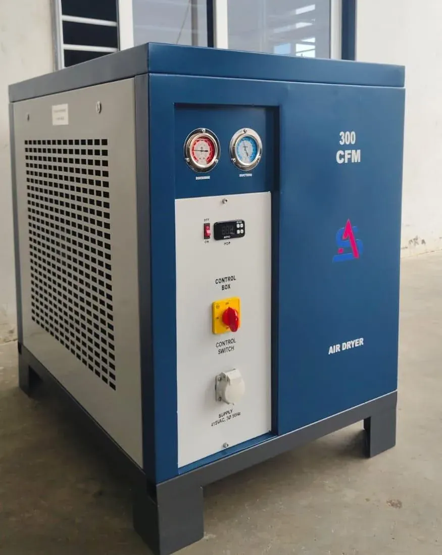
A refrigerated dryer cools compressed air so moisture condenses, separates liquid and typically reheats/allows the air to warm downstream. Exact architecture varies by product.
3 — Pressure Dew Point Is the Key Language
Preserve pressure and measurement basis when comparing requirements and performance.
4 — Application Envelope
Refrigerated drying is widely used for general industrial moisture control within supported dew-point ranges. Lower-moisture duties may require another architecture.
5 — Rated Flow Is Conditional
Catalogue flow is tied to stated pressure, inlet temperature, ambient/cooling condition and dew-point duty. Treat rating as conditional.
6 — Inlet Temperature Can Dominate Selection
Hotter compressed air carries greater moisture burden and can reduce effective capacity. Verify worst/representative inlet temperature after aftercooling.
7 — Inlet Pressure Influences Selection
Use manufacturer selection/correction data for actual pressure rather than assuming nameplate flow applies everywhere.
8 — Ambient Matters for Air-Cooled Dryers
Air-cooled condensers depend on ambient and ventilation. High room temperature or hot-air recirculation can reduce margin.
9 — Cooling Water Matters for Water-Cooled Dryers
Cooling-water temperature, flow and quality become part of selection and maintenance.
10 — Use Manufacturer Correction Methods
Apply the exact manufacturer's factors/tables/software and combination method. Do not import factors from another dryer family.
11 — Corrected Capacity Must Cover the Design Case
Compare supported corrected capacity with relevant normal/peak flow cases and record the basis.
12 — Peak Flow Needs Duration Context
Do not assume any transient overload is acceptable. Use manufacturer-backed guidance.
13 — Upstream Liquid Separation Protects the Dryer
Maintain aftercooler separation and drains; the dryer should not be the sole bulk-liquid device.
14 — Internal Heat Exchange Influences Operation
Air-to-air heat exchange can precool incoming air and reheat outgoing air; exact arrangement affects load and outlet condition.
15 — Refrigeration Circuit Must Stay Within Limits
Compressor, evaporator, condenser and expansion/control devices operate as a system. Service requires trained personnel and applicable compliance.
16 — Internal Temperature Is Not Automatically Dew Point
Evaporating temperature, separator temperature and measured pressure dew point are different quantities.
17 — Internal Condensate Separation Is Critical
Cooling creates liquid that must be separated before air exits the cold section.
18 — Dryer Drains Need Capacity and Reliability
Include internal drains in the plant drain register and maintenance plan.
19 — Pressure Drop Is a Lifecycle Cost
Evaluate supported clean/operating pressure drop; unnecessary loss can drive higher source pressure.
20 — Do Not Oversize Blindly
Select within supported range and growth strategy rather than choosing the largest unit.
22 — Cycling Dryers Need Load-Profile Review
Evaluate actual operating range, dew-point stability and control method.
23 — Non-Cycling Dryers Have Different Part-Load Behaviour
Compare exact product performance rather than labels alone.
24 — Variable-Speed Refrigeration Is Product-Specific
Assess supported control range, dew-point performance and energy data; do not assume fixed savings.
25 — Dryer Bypass Is a Quality Risk
Define valve control, authorisation, indication and process consequences.
26 — Parallel Dryers Need Balanced Engineering
Flow sharing, isolation, check valves, controls, drains and maintenance access require design.
27 — Duty/Standby Needs Changeover Philosophy
Define manual/automatic changeover and proof that standby can take required duty.
28 — Receiver Position Changes Dryer Duty
Wet receiver upstream and dry receiver downstream have different roles.
29 — Prefiltration Depends on Architecture
Follow compressor/dryer design and manufacturer instructions; no universal filter grade is prescribed.
30 — Downstream Filtration Has Separate Purpose
A dryer controls moisture, not every particulate/oil requirement.
31 — Installation Space Includes Service Access
Allow for airflow, condenser cleaning, drain/electrical/refrigeration service, filters, bypass and removal.
32 — Ventilation Can Decide Reliability
Include dryer heat rejection in compressor-room ventilation assessment.
33 — Electrical Integration Uses Exact Package Data
Review voltage/frequency, protection, starting/inrush, controls, alarms and communications.
34 — Dew-Point Monitoring Follows Consequence
Critical processes may justify calibrated monitoring, alarms or logging; general plant air may need less.
35 — Sensor Location Matters
Range, pressure, sample system, contamination, response, calibration and location affect readings.
36 — Commission Conditions, Not Just Power-On
Record inlet flow/pressure/temperature, ambient/cooling, drains, pressure drop, controls, alarms and moisture evidence.
37 — Trending Reveals Degradation
Dew point, pressure drop, inlet temperature, ambient and alarm history can reveal changing condition.
38 — Maintenance Protects Dew Point and Pressure
Condenser, drains, separator, heat exchangers, refrigeration circuit and sensors require exact manufacturer maintenance.
39 — Water Downstream Is Not Automatically Dryer Failure
Check upstream separation, bypass, drains, flow, inlet conditions and downstream condensation.
40 — Dew Point Alone Is Not Complete Acceptance
Also verify flow, pressure, operating conditions, pressure drop, drainage and measurement method.
41 — Seasonal Verification Can Matter
Cool-weather commissioning may not represent hot/humid duty.
42 — Expansion Requires Corrected-Capacity Recheck
Additional flow/moisture can consume apparent spare capacity.
43 — Temporary Compressor Connections Can Overload the Dryer
Rental air can arrive hotter, wetter or at different pressure/flow; recheck the existing dryer.
44 — End With an Evidence Record
Record exact model/configuration, rating conditions, corrections, supported capacity, pressure drop, dew-point duty, drains, filters, controls, site assumptions and acceptance method.
45 — Refrigerated Dryer Selection Register
Field | Required record |
|---|---|
Process requirement | Required moisture condition and boundary |
Design flow | Normal/peak case and airflow basis |
Inlet pressure | Relevant operating range |
Inlet temperature | Normal and worst/representative |
Ambient/cooling | Ambient air or cooling-water conditions |
Rated dryer data | Exact model, rated flow and conditions |
Correction method | Manufacturer factors/tables/software and revision |
Corrected capacity | Supported capacity under project conditions |
Pressure drop | Supported/expected at relevant flow |
Drainage | Separator/drain type, capacity and monitoring |
Filtration | Treatment interfaces |
Controls | Cycling/non-cycling/VSD, alarms, remote interface |
Verification | Dew-point/condition method and location |
Revision | Date, configuration, reviewer |
46 — Selection Calculation Workflow
Step | Controlled action |
|---|---|
1 | Freeze required pressure dew point/quality boundary |
2 | |
3 | |
4 | |
5 | Confirm ambient/cooling-water condition |
6 | Take exact dryer rating and basis |
7 | Apply manufacturer-approved correction method |
8 | Check corrected capacity against required flow |
9 | Check pressure drop, drains, filters and bypass |
10 | Define dew-point verification/commissioning method |
47 — Technical Verification Gate
Gate | Pass requirement |
|---|---|
RD1 | Moisture requirement/boundary defined |
RD2 | Pressure dew-point basis controlled |
RD3 | Design flow/basis defined |
RD4 | Inlet pressure reviewed |
RD5 | Inlet temperature reviewed |
RD6 | Ambient/cooling reviewed |
RD7 | Exact rating basis identified |
RD8 | Manufacturer correction method used |
RD9 | Corrected capacity supports case |
RD10 | Pressure drop visible |
RD11 | Bulk-liquid separation/drainage verified |
RD12 | Filtration interfaces defined |
RD13 | Bypass/redundancy controlled |
RD14 | Measurement method/location defined |
RD15 | Commissioning conditions recorded |
RD16 | Expansion/temporary-air changes trigger reselection |
49 — Frequently Asked Questions
How do I size a refrigerated air dryer?
Use required flow with inlet pressure, inlet temperature, ambient/cooling conditions, required pressure dew point and exact manufacturer rating/correction method.
Can I match dryer CFM to compressor CFM?
Not safely without checking rating bases and project conditions.
What pressure dew point does it provide?
Use exact manufacturer-supported performance for the selected model/conditions; no universal value is assumed.
Why does inlet temperature matter?
Hotter air can carry more moisture and reduce effective dryer capacity.
Does pressure affect sizing?
Yes. Use the manufacturer's method for actual pressure.
Cycling or non-cycling?
Compare load profile, dew-point stability, control method, energy and lifecycle needs.
Do I still need filters?
A dryer controls moisture; particulate/oil requirements need their own treatment architecture.
Why is water appearing downstream?
Check separation, drains, bypass, overload, inlet conditions, refrigeration condition and downstream condensation.
Can two dryers run in parallel?
Potentially, with engineered flow sharing, isolation, controls, drains and maintenance.
Should dew point be monitored continuously?
Monitoring level depends on process consequence and quality requirements.
What information is needed?
Flow, pressure, inlet temperature, ambient/cooling conditions, required dew point, compressor type, upstream separation/filters, utilities and redundancy needs.
52 — Final CTA
DO NOT SIZE A REFRIGERATED DRYER FROM COMPRESSOR CFM ALONE.
DEFINE THE DEW POINT. DEFINE THE FLOW. DEFINE THE PRESSURE. DEFINE THE INLET TEMPERATURE AND COOLING CONDITIONS. THEN CORRECT THE RATING.
Secondary CTAs: Submit Dryer Duty • Review Moisture Problem • Review Filtration • Review Existing Dryer Capacity
Checkpoint Record
Future revisions require a new version identity.
V2 expands refrigerated-dryer thermodynamics, selection, correction, controls, integration, diagnostics, commissioning and lifecycle engineering without deleting V1.
V2 STATUS: STAGING READY — TECHNICAL / EDITORIAL VERIFICATION GATED
V2.1 — Start With the Moisture Requirement
Select a refrigerated dryer from the required moisture condition at a defined boundary, not compressor CFM alone. Control pressure-dew-point basis, flow cases, inlet pressure/temperature, ambient or cooling-water condition, pressure drop and process consequence.
V2.2 — Refrigerated Drying Physics
The dryer cools compressed air so vapour condenses, separates and drains liquid, and commonly reheats outgoing air through internal heat exchange. Refrigeration, separation and drainage are distinct functions that must all work.
V2.3 — Pressure Dew Point Is Not Evaporator Temperature
Delivered pressure dew point, refrigerant evaporating temperature and internal surface temperature are different quantities. Preserve the manufacturer's supported relationship and measurement method.
V2.4 — Define the Compliance Boundary
State whether the moisture requirement applies at dryer outlet, dry receiver, plant header or point of use. Downstream cooling, bypasses, wet branches and recontamination can change the condition.
V2.5 — Rated Flow Is Conditional
Catalogue capacity is tied to rating conditions such as inlet pressure, inlet temperature, ambient/cooling condition and moisture duty. Nominal CFM is not universal capacity.
V2.6 — Inlet Temperature Can Dominate Sizing
Hotter air can carry a greater moisture burden and increase refrigeration load. Verify actual aftercooler outlet/dryer inlet temperature under relevant ambient and compressor-load conditions.
V2.7 — Inlet Pressure Influences Effective Capacity
Operating pressure changes air density and dryer duty. Use the exact manufacturer's pressure correction/selection method rather than a generic factor.
V2.8 — Ambient Matters for Air-Cooled Dryers
High ambient, dirty condenser surfaces or hot-air recirculation can reduce heat rejection and operating margin. Compressor-room ventilation must include dryer heat rejection.
V2.9 — Cooling Water Matters for Water-Cooled Dryers
Entering water temperature, flow and quality influence condenser performance. Scaling, fouling and insufficient flow can reduce capacity.
V2.10 — Correction Factors Are Product-Specific
Use the exact manufacturer's tables, factors or software and preserve the combination method. Never import factors from another dryer family.
V2.11 — Worked Corrected-Capacity Logic
Illustrative only: a dryer rated at 25 m3/min under stated conditions receives an invented combined project factor of 0.80 under the manufacturer's hypothetical method. Corrected capacity would be 20 m3/min. If duty is 22 m3/min, the candidate fails. The 0.80 factor is educational only and must never be reused.
V2.12 — Corrected Capacity Must Cover the Design Case
Any transient overload acceptance must come from manufacturer-supported guidance.
V2.13 — Upstream Bulk-Liquid Removal Protects the Dryer
The dryer should not be expected to compensate for failed upstream drains or excessive liquid carryover.
V2.14 — Air-to-Air Heat Exchange
Many dryers precool incoming air and reheat outgoing air using internal air-to-air exchange. Exact arrangement affects refrigeration load, outlet temperature and downstream condensation risk.
V2.15 — Refrigeration Circuit as a System
Refrigeration compressor, condenser, expansion/control device, evaporator and controls operate together. Service requires appropriate competence and exact equipment procedures.
V2.16 — Internal Condensate Separation
Cooling creates liquid that must be separated before air exits the cold section. A healthy refrigeration circuit with a failed separator/drain can still produce downstream water.
V2.17 — Dryer Drain Engineering
Verify drain capacity, contamination tolerance, operating pressure, isolation, discharge routing and alarm/inspection requirements.
V2.18 — Pressure Drop Is Part of Dryer Duty
Heat exchangers, separators and passages create pressure loss. Track supported and operating differential; do not hide avoidable restriction by increasing compressor pressure.
V2.19 — Oversizing Is Not Automatically Premium
Extra capacity can be useful, but unnecessary oversizing raises capital and can affect control behaviour. Select within supported range and credible expansion plans.
V2.20 — Average Flow Can Undersize the Dryer
Average plant demand can hide long high-production periods. Use controlled sustained and peak cases, not monthly average compressor output.
V2.21 — Cycling Dryers
Evaluate exact cycling/storage/control method, dew-point stability, minimum load, restart behaviour and energy data. The label alone does not prove suitability.
V2.22 — Non-Cycling Dryers
Continuously operating refrigeration architectures can offer stable operation but have different part-load characteristics. Compare exact products rather than labels.
V2.23 — Variable-Speed Refrigeration
Verify supported speed/control range, dew-point performance, minimum load and input-power data. Do not claim a fixed energy-saving percentage.
V2.24 — Hot-Gas Bypass and Capacity Control
Some systems use hot-gas bypass or other controls at reduced load. Maintenance teams should understand the exact control philosophy before interpreting refrigeration pressures or energy.
V2.25 — Freeze Protection
The cold-side design must avoid unwanted freezing while maintaining supported moisture performance. Lower internal temperature is not automatically better.
V2.26 — Bypass Is a Quality Risk
A bypass can preserve supply while sending wet air downstream. Define valve positions, authorisation, indication and process response.
V2.27 — Parallel Dryer Architecture
Parallel dryers require flow distribution, isolation, check valves, drains, controls and maintenance access. Unequal pressure drop can overload one unit.
V2.28 — Duty/Standby Architecture
A standby dryer must be capable of taking the defined flow/moisture duty. Define pressurisation, changeover, readiness testing and expected dew-point behaviour during transition.
V2.29 — Wet and Dry Receivers
Wet receivers can support cooling and liquid collection; dry receivers store treated air. Position affects dryer loading, transient flow and stored-air quality.
V2.30 — Filtration Interfaces
Upstream/downstream filtration follows compressor technology, dryer requirements and process quality. No universal filter grade or sequence is prescribed.
V2.31 — Installation and Service Clearance
Allow condenser airflow, cleaning, drain/refrigeration/electrical access, filters, bypass operation and equipment removal.
V2.32 — Compressor-Room Heat Balance
Air-cooled dryers reject heat into the room. Poor ventilation can simultaneously worsen compressor and dryer performance.
V2.33 — Electrical Integration
Confirm voltage, frequency, protection, load/inrush where relevant, controls, alarms and communications using exact package data.
V2.34 — Dew-Point Monitoring Strategy
Monitoring level follows process consequence. Sensor location, sample conditioning, pressure, contamination, calibration and response time affect readings.
V2.35 — Worked Hot-Weather Scenario
Illustrative only: moisture performance deteriorates during hot afternoons. Before upsizing, verify aftercooler outlet temperature, room ventilation, condenser cleanliness, inlet flow/pressure, ambient and drain operation.
V2.36 — Worked Pressure-Drop Scenario
Illustrative only: downstream pressure gradually declines while compressor setpoint is unchanged. Differential measurement shows increasing treatment loss. Inspect filters, exchangers and restrictions before raising source pressure.
V2.37 — Worked Peak Scenario
Illustrative only: sustained flow is within corrected capacity but repeated short peaks exceed it. Review duration/frequency, manufacturer transient guidance, receiver arrangement and moisture consequence before accepting or rejecting the dryer.
V2.38 — Commissioning Must Verify Conditions
Record identity, rating basis, corrections, inlet flow/pressure/temperature, ambient/cooling condition, pressure drop, drains, controls, alarms and agreed moisture evidence.
V2.39 — Establish a Baseline Trend
Retain initial dew point, inlet temperature, ambient condition, pressure drop and relevant control observations for later comparison.
V2.40 — Troubleshooting High Dew Point
Check actual flow, inlet temperature/pressure, ambient/cooling, upstream liquid removal, drains, bypass, refrigeration condition, sensor accuracy and downstream recontamination.
V2.41 — Troubleshooting Water Downstream
Visible water can result from failed upstream drains, dryer overload, internal drain/separator problems, bypass or downstream condensation. Locate where liquid first appears.
V2.42 — Maintain Air-Cooled Condensers
Condenser cleanliness and unobstructed airflow are critical. Maintenance frequency follows site dust and equipment requirements.
V2.43 — Maintain Water-Cooled Condensers
Monitor water-side fouling, flow, temperature and quality. Scaling can progressively reduce heat rejection.
V2.44 — Refrigeration-Circuit Maintenance
Use trained personnel and exact manufacturer procedures.
V2.45 — Sensor and Control Maintenance
Dew-point/temperature sensors, pressure devices, drains and controllers can drift or fail. Include verification/calibration and functional testing.
V2.46 — Seasonal Verification
A dryer accepted in mild weather may face greater moisture and heat-rejection duty in hotter/humid periods. Preserve the design environmental case.
V2.47 — Expansion Reopens Corrected Capacity
Additional compressors, higher production, changed pressure or hotter inlet conditions can consume apparent spare capacity. Re-run the exact selection method.
V2.48 — Temporary Compressor Integration
Rental compressors can deliver hotter/wetter air or different oil carryover. Verify compatibility with aftercooling, filtration and dryer capacity before connection.
V2.49 — Energy Evaluation
Compare dryer electrical input, pressure-drop consequence and control behaviour across the actual load/ambient profile. Quality stability remains the governing boundary.
V2.50 — Lifecycle Cost
Include purchase, electrical energy, pressure-drop energy, maintenance, drains, filters, refrigeration service, downtime risk, monitoring and expansion.
V2.51 — Evidence Hierarchy
Distinguish manufacturer rating data, project-specific selection output, calibrated measurements, dew-point measurements, service data and engineering estimates.
V2.52 — Common Engineering Mistakes
Avoid nameplate-CFM matching without conditions, generic correction factors, evaporator-temperature/dew-point confusion, ignored aftercooling, ignored pressure drop, uncontrolled bypass, fixed savings claims and low-load-only acceptance.
V2.54 — Premium Refrigerated-Dryer Selection Register
Field | Controlled record | Why it matters |
|---|---|---|
Required moisture | Pressure dew point / boundary | Defines dryer duty |
Design flow | Sustained/peak + basis | Capacity requirement |
Inlet pressure | Normal/min/max | Selection correction |
Inlet temperature | Normal/critical | Moisture/refrigeration load |
Ambient/cooling | Air or water conditions | Heat-rejection capability |
Rated data | Exact model + rating conditions | Source evidence |
Correction method | Exact manufacturer method/revision | Project capacity |
Corrected capacity | Supported project-condition flow | Sizing decision |
Pressure drop | Supported/operating | |
Drainage | Internal separator/drain | Liquid removal |
Controls | Cycling/non-cycling/VSD/other | Part-load behaviour |
Verification | Dew point method/location | Acceptance |
Maintenance | Condenser/drain/sensors/refrigeration | Lifecycle reliability |
V2.55 — Dryer Troubleshooting Evidence Matrix
Symptom | First evidence to collect | Do not assume |
|---|---|---|
High dew point | Flow, inlet temp/pressure, ambient, sensor, controls | Refrigerant shortage |
Visible water | Upstream drains, dryer drain, bypass, downstream cooling | Dryer alone failed |
High pressure drop | Flow + differential across treatment | Need higher compressor pressure |
High-temp trip | Ambient, condenser condition, ventilation/water flow | Dryer undersized |
Frequent cycling | Load profile + control state | Control fault |
Poor hot-weather performance | Aftercooler inlet temp + ambient/cooling | Nameplate capacity applies unchanged |
V2.56 — Technical Verification Gate
Required moisture condition and compliance boundary are defined.
Pressure-dew-point basis is controlled.
Design flow and airflow basis are controlled.
Inlet pressure and temperature cases are verified.
Ambient or cooling-water design condition is verified.
Exact dryer rating conditions are identified.
Manufacturer correction method is used correctly.
Corrected capacity supports relevant design cases.
Upstream bulk-liquid removal is verified.
Drain and filtration interfaces are controlled.
Bypass/parallel/standby philosophy is defined.
Dew-point monitoring method/location are defined.
Commissioning captures actual operating conditions.
Seasonal/expansion/temporary-air changes trigger reassessment.
Manufacturer-specific performance remains evidence-gated.