
Reddy Compressors
Temporary compressed-air distribution must deliver the required pressure and flow to each active user through an installation that remains mechanically suitable, identifiable and maintainable throughout the hire period. Compressor capacity alone cannot establish that outcome. A restrictive coupling, an undersized shared hose or an unsuitable manifold can limit useful delivery even when the compressor has spare capacity.
This guide develops the supplied rental-accessory and installation material into practical guidance for temporary mains, hoses, manifolds and branches. It covers flow allocation, pressure-loss assessment, assembly compatibility, site routing, stored pressure, cleanliness, commissioning and changes during operation. Worked values are hypothetical examples, not manufacturer ratings, quotations or measured Reddy Compressors project results.
01 Define the distribution boundary
Identify where the temporary distribution starts and ends. It may connect a rental compressor to a plant header, a treatment package to several process users or a manifold to construction tools. State whether aftercoolers, dryers, regulators and local accessories are included in the pressure and flow boundary. Otherwise, two suppliers may describe the same delivery requirement while including different equipment losses.
Record the minimum operating pressure, maximum permitted pressure, simultaneous flow and required air quality at each receiving point. Note the expected duration and any planned movement of equipment or users. A route suitable for a short supervised trial may not be suitable for continuous service across vehicle movements, weather exposure and several shifts.
Separate different services. Ordinary tool air, instrument air, high-pressure supply and breathing air must not be treated as interchangeable outlets on one convenient manifold. Specialist duties require their own specifications and connection controls. The arrangement should make an incorrect connection difficult to make and easy to identify before air is introduced.
02 Draw the actual route and connection schedule
Create a marked plan showing the source, treatment, main line, manifolds, branch lines and delivery points. Record actual route lengths, internal diameters, fittings, isolation points, crossings, supports and measurement locations. Include loops needed for movement and the installed route around obstacles rather than using straight-line distance between the compressor and the process.
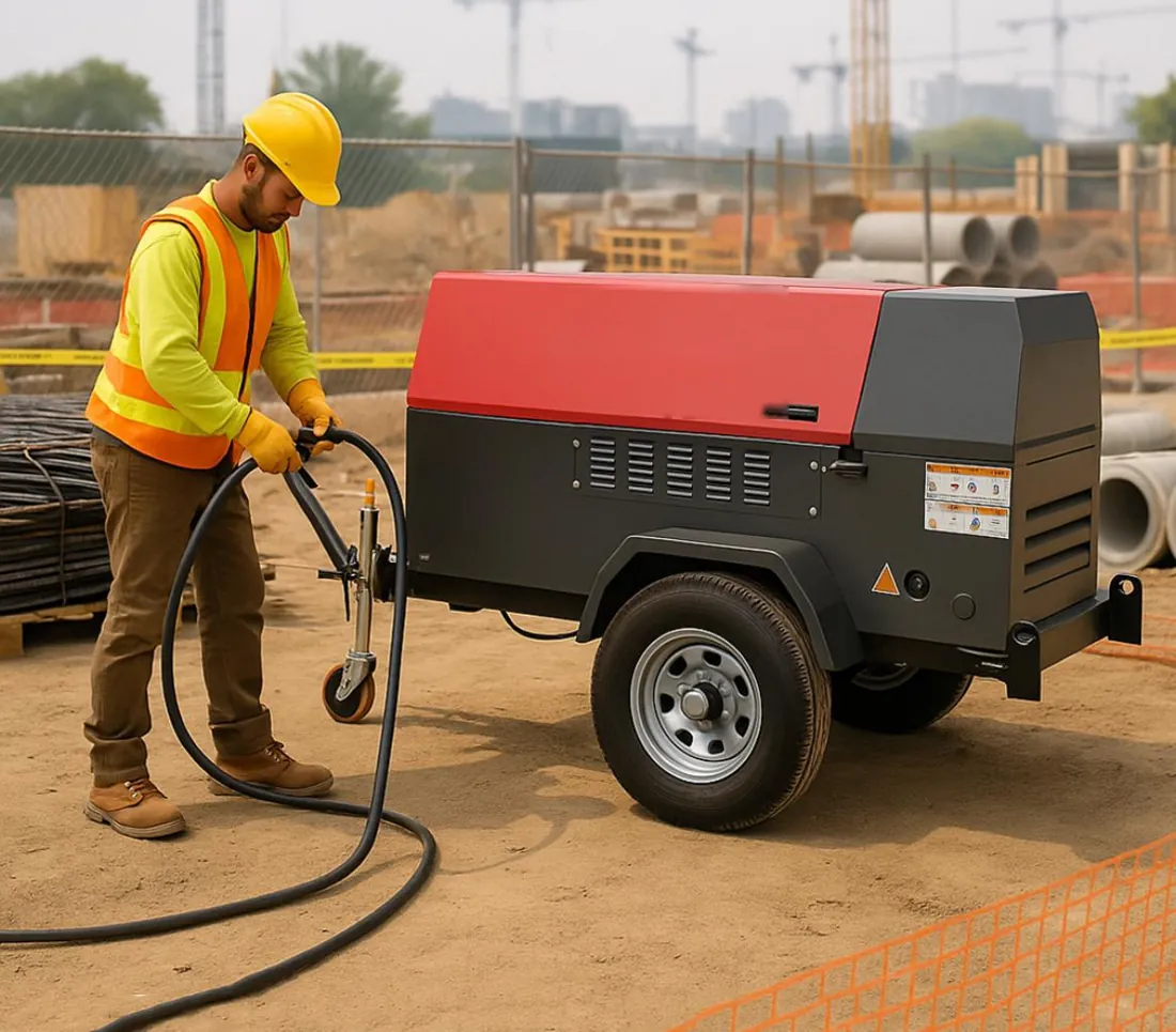
Give each hose assembly and branch a recognisable identity. Link that identity to length, size, service rating and inspection status. At a multi-contractor site, a simple current schedule helps prevent an unapproved extension or a higher-pressure source being connected to an assembly intended for another duty.
Show how the route changes during the project. Excavation, scaffolding, temporary roads and material storage can remove access or introduce mechanical hazards. Assign responsibility for checking proposed changes. A photograph of the accepted arrangement is useful, but it should supplement the route record rather than replace the information needed to assess flow, ratings and isolation.
03 Allocate simultaneous demand to every segment
Each shared segment must carry the combined demand downstream of it under the relevant operating scenario. A main feeding three branches should not be sized from the largest branch alone. Conversely, a branch only needs to carry its own defined users, provided the operating arrangement prevents other loads from being added without reassessment.
The following example uses assumed flows on the same reference-air basis. No tool or process rating is implied.
Segment or user | Assumed demand | Distribution implication |
|---|---|---|
Branch A | 4.0 m³/min | Assess its full route and local accessories |
Branch B | 3.0 m³/min | Check simultaneous operation with A and C |
Branch C | 2.0 m³/min | Keep its pressure and quality requirement explicit |
Shared auxiliaries | 0.5 m³/min | Identify where the consumption enters the network |
Common main | 9.5 m³/min | Carries all listed simultaneous demand |
If only A and B may operate together under a controlled schedule, the corresponding main duty is 7.5 m³/min including auxiliaries. That lower figure depends on an enforceable schedule. Do not apply an unexplained diversity factor to every branch and assume the common main will remain adequate during a busy interval or restart.
04 Reconcile reference flow and actual flow
Compressor and tool data often describe flow as free air or at stated reference conditions, while velocity calculations require the actual volume moving inside the line. Keep these definitions explicit. Combining reference flow with actual pipe area without conversion can produce a misleading velocity and an incorrect assessment of pressure loss.
For an ideal-gas screening conversion, actual flow equals reference flow multiplied by reference absolute pressure divided by line absolute pressure, then multiplied by line absolute temperature divided by reference absolute temperature. Apply compressibility corrections where relevant. Gauge pressure must first be converted to absolute pressure using the applicable atmospheric pressure.
For illustration, 10 reference m³/min at 1 bara and 20°C becomes approximately 10 × (1 ÷ 8) × (303.15 ÷ 293.15) = 1.293 actual m³/min at 8 bara and 30°C. This assumes compatible dry-air bases and ideal-gas behaviour. It is not a complete pressure-drop calculation because line pressure and therefore local density change along the route.
05 Use internal diameter for velocity assessment
The working flow area depends on internal diameter, not hose outside diameter or nominal coupling size. Obtain the actual bore of the proposed hose and identify smaller passages in adapters, valves and connectors. A short reduced-bore fitting can affect delivery even when the main hose appears generously sized.
Using the illustrative actual flow of 1.293 m³/min, a 50 mm internal diameter has an area of π × 0.05² ÷ 4 = 0.001963 m². Average velocity is approximately (1.293 ÷ 60) ÷ 0.001963 = 11.0 m/s. A 38 mm internal diameter gives an area of approximately 0.001134 m² and a velocity of 19.0 m/s at the same local flow.
These figures compare geometry; they are not universal acceptable-velocity limits or final hose selections. Assess pressure loss, operating pressure, noise, transient behaviour, manufacturer limits and the actual application. A velocity calculation is one input to selection. It cannot establish the mechanical suitability, cleanliness or coupling compatibility of an assembly.
06 Calculate pressure loss with an appropriate method
Use manufacturer pressure-loss data or a suitable compressible-flow calculation for the actual hose, fittings, pressure, temperature and reference-flow definition. Document the method and assumptions. Different hose constructions and coupling passages can make a generic pipe chart a poor substitute for product-specific information.
For modest pressure changes, a Darcy-Weisbach calculation using representative density can support a screening estimate: pressure loss is proportional to friction factor, length divided by diameter, density and velocity squared. Under similar flow conditions and approximately constant friction factor and density, the straight-run loss scales roughly with length and with flow squared, and inversely with diameter to the fifth power.
That relationship explains why a modest increase in bore can have a substantial effect, but it must not be extended uncritically to large pressure ratios, changing friction factors or restrictive connectors. For example, the approximate straight-hose loss ratio for 50 mm versus 38 mm bore is (38 ÷ 50)⁵ = 0.254 under those assumptions. This suggests about one quarter of the straight-run loss, not a guaranteed 75% reduction for the whole installation.
07 Include couplings valves and local accessories
Assess the complete series of components in the flow path. Quick couplings, elbows, reducers, non-return valves, safety devices, regulators and filters all have flow characteristics. Use published gas-flow data where available and respect its test conditions. A connection with a large external thread can still have a restrictive internal passage.
Avoid double-counting fitting losses if a manufacturer’s assembly curve already includes its standard end connections. Equally, do not omit extra adapters added on site. Document whether an equivalent-length allowance, a loss coefficient or a product flow curve was used. This makes later changes traceable and keeps the calculation tied to the installed hardware.
A regulator’s ability to maintain downstream pressure depends on flow and inlet conditions; its nominal setpoint is not a guarantee at every demand. Include any required minimum inlet-to-outlet pressure difference and check response during events. Select local filtration and lubrication for the receiving equipment, and keep incompatible quality requirements out of a shared lubricated branch.
08 Build the pressure budget to the limiting user
Work backward from the user that combines a demanding pressure requirement with a restrictive route. The farthest user is often important, but it is not automatically the limiting one. A closer branch with a small regulator or high instantaneous flow may experience the greatest pressure deficit.
Suppose the required user inlet pressure is 6.0 barg. Assumed losses at the simultaneous duty are 0.30 bar in treatment, 0.35 bar in the shared main, 0.15 bar in the manifold, 0.25 bar in the branch and 0.20 bar in local accessories. Total loss is 1.25 bar, giving an upstream requirement of 7.25 barg before assessing the control band and other justified allowances.
If the source supplies only 7.0 barg at the relevant flow, the simplified budget leaves 5.75 barg at the user. Investigate the limiting components or revise the distribution arrangement. Increasing source pressure requires assessment of every downstream maximum rating and operating limit; it is not an automatic remedy. Verify the budget by measuring pressure under representative load.
09 Select the hose for its complete service
Specify a hose and assembly suitable for compressed air at the required working pressure, temperature and environmental exposure. Include compressor-outlet conditions where the line is upstream of cooling. A hose that is suitable downstream of treatment may not be suitable for a hotter connection nearer the compressor.
Review compatibility with compressor lubricant, condensate, cleaning agents and the external environment. Consider abrasion, weather, sunlight, chemicals and movement. Use manufacturer instructions for pressure-temperature limitations, minimum bend radius and installation. General hose guidance supports this selection process but does not prove that a particular hydraulic or industrial hose is approved for the intended air service.
The assembly rating must account for both hose and fitted ends under the relevant conditions. Burst pressure is not permissible working pressure. A test record does not erase damage or establish unlimited service life. Keep manufacturer identification and applicable inspection records available so replacement decisions can be made from evidence rather than appearance or colour alone.
10 Verify connection compatibility and assembly integrity
Confirm the exact coupling family, size, seal material, locking arrangement and rated duty. Similar-looking connections are not necessarily interchangeable. Check threads and sealing methods against the specified components, especially where adapters connect temporary equipment to permanent piping. Improvised mixed assemblies can introduce both leakage and mechanical failure risk.
Use fittings and assembly methods approved for the hose and application. If an assembly is repaired or rebuilt, require competent work and the appropriate verification before return to service. Do not tighten, disconnect or attempt to correct a leaking pressurised joint as an ordinary operating adjustment. Establish isolation and verified pressure release first.
Inspect sealing faces, locking elements, ferrules and the hose near the ends, where bending and handling can concentrate damage. Support the route so the coupling does not carry avoidable pull or weight. A mechanically compatible joint still needs suitable flow capacity and cleanliness; connection compatibility is necessary but is not the whole selection.
11 Distinguish restraints from automatic flow protection
A restraint limits movement if an assembly separates within its intended design conditions. An automatic hose-failure device can reduce air flow following a defined failure. Positive locking helps prevent accidental disconnection. These functions are different, and one should not be described as a universal replacement for the others.
Select protection for the actual hose, flow, pressure and failure scenario. A flow-sensitive device must permit normal demand yet respond as intended to the relevant failure; behaviour can depend on downstream restrictions and available upstream flow. Obtain the supplier’s selection and installation requirements instead of assuming that any device with the correct thread will work.
OSHA’s United States construction-tool standard addresses positive hose connections, tool retainers, pressure limits and hose-failure protection for specified pneumatic-tool arrangements. It is an international reference here, not a declaration of Indian legal requirements. Establish the rules applicable to the project and the equipment. Never use an air hose to lift or lower a tool, and do not improvise restraints from unsuitable materials.
12 Design manifolds for the combined duty
A manifold distributes flow; it does not create additional compressor capacity. Size its inlet and internal passages for the combined duty, then assess each outlet for its branch flow and pressure requirement. Count restrictions in inlet valves, outlet valves and adapters. Several large outlet ports do not prove that the common inlet can supply them simultaneously.
Provide identifiable isolation for the intended branches and ensure that unused outlets are secured with suitable rated components. Keep operating positions and service identities clear. Where different users need different pressures, assess appropriate branch regulation and protection rather than relying on operators to partly close an isolation valve as a pressure-control method.
Support the manifold and protect it from vehicle impact, dropped objects and hose pull. Maintain access to controls, instruments and drains where fitted. A manifold used to combine compressor sources needs a separate review of backflow, controls, ratings and permitted parallel operation. A product marketed as a distribution manifold should not automatically be used as a multi-source combining header.
13 Choose a topology that fits the project
A main with individual branches can simplify identification and isolation. Separate dedicated lines may suit users with different quality or pressure requirements. A ring or dual-fed arrangement may offer alternative flow paths, but its performance and isolation become more complex. Select the topology from the duty and site rather than copying a permanent factory layout into a temporary installation.
Layout | Practical advantage | Main issue to resolve |
|---|---|---|
One main with branches | Clear distribution from a common source | Shared-main pressure loss and common failure |
Dedicated user lines | Distinct pressure and quality boundaries | More routing, connections and handling |
Ring or dual feed | Potential alternative flow paths | Network balance, backfeed and isolation complexity |
Local supplementary package | Shorter route for a remote high-demand user | Independent utilities and clear connection boundary |
Equal-length parallel hoses do not necessarily share flow equally when their fittings and internal conditions differ. Assess the actual network. If one path is isolated, verify that the remaining path can support the required service rather than assuming that a two-path layout is automatically redundant.
14 Route for traffic movement and site access
Identify vehicle crossings, pedestrian routes, emergency access, excavation edges, lifting zones and locations exposed to heat or sharp debris. Arrange suitable protection and supports for the loading and environment. A cover intended for pedestrians may not be suitable for construction vehicles; the protective arrangement needs its own site assessment.
Maintain manufacturer bend-radius requirements and avoid twisting, crushing and unsupported weight at connections. Allow for intended equipment movement without creating a snagging loop. Elevation changes and suspended sections need appropriate support, and a hose should not become a substitute for a lifting or structural component.
Keep isolation accessible when the site is busy. A valve hidden behind stored material is less useful during a fault. Coordinate the route with other contractors and update it when the site changes. For long-duration or high-flow duty, compare an appropriate temporary rigid main with flexible connections against a route made entirely of repeated hose extensions.
15 Manage condensate and preserve delivered quality
Air can cool along an outdoor route and form condensate if its moisture content permits. Low sections can collect liquid and intermittently send it downstream. Identify where drainage is needed, how it can be performed safely and where condensate will be collected. Do not assume that an upstream separator prevents all downstream liquid formation.
Keep downstream quality requirements visible when selecting hoses, manifolds and receivers. A clean treatment outlet can be compromised by an assembly previously used in a contaminated service. Protect open ends during handling and use a suitable preparation and verification method before connecting sensitive processes. Do not clear an uncertain line by discharging its contents into the process header.
Point-of-use lubrication must remain confined to equipment that requires it. If instrument or quality-sensitive air shares the source, maintain an appropriate separation from lubricated tool branches. The final acceptance boundary should reflect the installed distribution, not just the treatment skid.
16 Account for stored pressure and filling demand
Hoses and manifolds contain compressed air even after the compressor stops. Non-return valves, closed regulators and isolated branches can trap it. The isolation method must identify these sections and verify pressure release before disconnection or intervention.
For scale, a 100 m hose with a 50 mm internal diameter has a geometric volume of π × 0.05² ÷ 4 × 100 = 0.196 m³. At 8 bara and equal temperature, it contains approximately 1.57 m³ expressed at a 1 bara reference. The additional inventory above atmospheric pressure is approximately 0.196 × (8 − 1) = 1.37 reference m³. These quantities are not a stored-energy calculation or a guarantee of usable reserve.
Filling this route also consumes air and can impose a transient on the source and treatment. Establish a controlled, equipment-appropriate filling and checking method. Do not count hose inventory as a dependable replacement for engineered storage; pressure at the user can fall rapidly, and the delivery rate depends on the whole flow path.
17 Commission under representative simultaneous flow
Confirm the route, assembly identities, ratings, coupling compatibility, supports, protection, branch labels and isolation before introduction of air. Verify cleanliness and any required inspection or test evidence. The project-specific commissioning method must establish controlled energisation, safe leak checking and response to an abnormal condition without exposing people to an unrestrained assembly.
Measure pressure at the source, manifold and limiting delivery point while the agreed users operate. Record flow where practicable, the active branches, source control state and relevant temperatures. Compare the measured distribution loss with the budget. A static pressure check can reveal some issues but cannot establish performance at the required flow.
Retain the accepted route and settings as the operating reference. Identify what changes require another check: added consumers, longer hoses, replacement couplings, a different source pressure or a new work zone. A successful trial applies to its tested configuration; it should not be treated as permanent approval for an expanding network.
18 Diagnose pressure loss before adding compressor capacity
Use measurements to locate the limiting boundary. If source pressure remains stable while manifold pressure falls, investigate the main and its components. If the manifold remains stable while one user falls, inspect that branch, regulator and accessories. If pressure falls throughout the network with the source at its delivery limit, assess total demand and source performance as well as leakage.
Consider a hypothetical simultaneous-flow test showing 7.2 barg after treatment, 6.6 barg at the manifold and 5.9 barg at the user. The measured main loss is 0.6 bar and the downstream branch loss is 0.7 bar. A no-flow user reading of 7.1 barg would not contradict this result; it would simply describe a different condition.
If the user needs 6.2 barg during operation, the observed shortfall is 0.3 bar. A proposed branch improvement should demonstrate that it recovers sufficient pressure at the same duty. Keep tool or process condition in the diagnosis: a worn or faulty user may consume excess air. Do not attribute every pressure complaint to a small compressor or every performance complaint to the hose.
19 Manage changes and compare the complete cost
Record additions and substitutions throughout the hire period. An extra 2.0 m³/min user added to the earlier 9.5 m³/min main increases demand to 11.5 m³/min. Under an approximate similar-condition flow-squared relationship, the straight-run loss ratio is (11.5 ÷ 9.5)² = 1.47. The approximate 47% increase illustrates why a modest new load can expose a previously acceptable restriction; verify the actual assembly rather than using the ratio as a final prediction.
Compare total support cost for alternatives that meet the same duty. A larger main, shorter route or local compressor may change hire, installation, handling, energy and supervision. For an illustrative choice, an improved distribution arrangement costs ₹1,500 more per day and ₹20,000 extra to install. If a controlled site comparison demonstrates ₹2,500 per day in combined operating benefit, the net benefit is ₹1,000 per day and simple recovery of the extra installation cost takes 20 days. A ten-day job would not recover that cost under these assumptions.
Benefits must be evidenced and comparable; pressure recovery alone does not prove energy or productivity savings. For an enquiry, send the user schedule, pressure and quality needs, route drawing, lengths, connection details and likely changes. Reddy Compressors can assess the temporary distribution requirement for Hyderabad, Secunderabad, Telangana, Andhra Pradesh and other requested project locations subject to configuration and support confirmation.
20 Frequently asked questions
How do I choose a temporary air hose size
Start with the simultaneous flow and required pressure at the delivery point. Use actual internal diameter, installed length, fittings and operating conditions to assess pressure loss. Then confirm the complete assembly’s pressure, temperature, compatibility and installation limits. Compressor outlet size alone is not a sufficient selection method.
Why is pressure normal until the tools begin working
Little or no flow produces little distribution loss. Once tools consume air, restrictions in the hose, manifold, couplings or local accessories can reduce pressure at the user. Measure the source and downstream points during representative operation. The results distinguish a distribution restriction from a source-capacity limitation more reliably than a static gauge reading.
Can two smaller hoses replace one larger hose
They can be evaluated as a parallel arrangement, but their combined performance depends on flow sharing, fittings and pressure loss. Two hoses with the same nominal size do not automatically provide equal flow. Check the arrangement with both paths available and any required one-path condition, together with isolation, protection and handling requirements.
Is a hose restraint enough to prevent a failure
A restraint does not make an unsuitable or damaged assembly acceptable and does not necessarily stop airflow. Correct hose selection, compatible connections, installation, inspection and the applicable failure-protection arrangement remain necessary. Select each protective device for its intended function and follow the relevant manufacturer and site requirements.
Can the manifold supply every outlet at its full rating
Only if the source, common main, manifold inlet and internal passages support that simultaneous duty while maintaining the required outlet conditions. Individual connection ratings do not establish combined flow capacity. Build a user schedule and assess the shared sections before adding loads or promising that all outlets can operate together.
Can a hose be disconnected after the compressor is stopped
Stopping the compressor does not prove that the hose is depressurised. Closed valves and other components can trap compressed air. Follow the site-specific isolation and verified pressure-release method for the actual assembly before disconnection. Never rely on elapsed time or a source-side gauge alone to establish a safe downstream condition.
Sources and evidence basis
22 Sources and engineering provenance
[S1] User-supplied 12-Air-Compressors-broucher.pdf, accessories section. Reviewed content identifies temporary hoses, manifolds, regulators and hose restraints as rental-system components. Historical product claims and capacity ranges are not presented as current Reddy Compressors specifications.
[S2] User-supplied 11-B.A.-19-7-26-RC-Tips.pdf, installation guidance. Reviewed passage addresses pipe sizing, pressure loss and drainage considerations.
[S3] Occupational Safety and Health Administration, 29 CFR 1926.302, Power-operated hand tools. Primary United States construction reference for pneumatic-tool connections, equipment pressure limits, hose handling and failure protection. Local applicability must be determined separately. https://www.osha.gov/laws-regs/regulations/standardnumber/1926/1926.302
[S4] Parker Hannifin, industrial hose and hose-safety literature. Primary manufacturer reference for service-specific assembly selection, ratings, routing and bend limitations. General guidance is not approval of a particular hose for this duty. https://www.parker.com/content/dam/Parker-com/Literature/Hose-Products-Division/Websphere-Supporting-Literature/Catalog-4800-Parker-Industrial-Hose.pdf
All example flows, sizes, losses, pressures, costs and benefits are assumed for illustration. Ideal-gas and approximate friction relationships are screening tools with their stated limitations, not final product selection methods. Actual distribution performance and any claimed savings require applicable equipment data and measurements.