
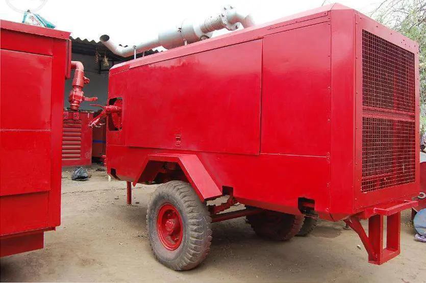
Reddy Compressors
Temporary-air redundancy is the demonstrated ability to maintain a defined air service after a specified failure. It depends on surviving net capacity, delivered pressure, air quality, recovery time and the dependencies shared by the remaining equipment. Another compressor on site is useful only when the complete arrangement can deliver the required service when called upon.
This guide helps plant engineers, maintenance teams and rental coordinators define failure cases, select a suitable backup arrangement and manage a loss of supply. It develops the supplied Reddy Compressors principle that machine redundancy alone does not establish system redundancy. All numerical examples are hypothetical. Physical switching, isolation, testing and repair must follow the approved site method and equipment instructions.
01 Define the service that must survive
Start with the consequence of losing air. Some users can pause with limited disruption; others need air to complete a controlled process transition, maintain a specified condition or protect product quality. The plant authority must define those consequences and the required response. A rental supplier cannot infer the correct process response from compressor capacity alone.
Specify the essential flow, minimum and maximum pressure at the receiving boundary, air-quality requirements, permitted interruption and required support duration. Identify whether the objective is full production, reduced production, completion of a batch or a controlled shutdown. These are different duties and may lead to different redundancy arrangements.
Define the operating envelope in which the claim applies. A station may survive one unit loss at normal demand but not during a production restart or cleaning peak. State those limits directly. Avoid presenting a normal-load capacity check as evidence that every possible combination is protected.
Retain the accepted boundary. Air available upstream of a failed dryer does not count as useful supply when the receiving process requires treated air. Likewise, sufficient flow at the package is not enough if the temporary distribution cannot maintain critical user pressure.
02 Separate reserve capacity from recovery capability
Reserve capacity describes how much useful output can be provided beyond the current duty. Recovery capability describes how and when that output becomes available after a failure. Both matter. A stopped spare might restore production after several minutes while offering no protection against a pressure interruption lasting seconds.
Distinguish installed spare equipment, connected standby, running reserve and off-site replacement. For each, state the actual readiness conditions: utility supply, treatment state, control mode, connection status, staffing and verification. Terms such as hot standby and cold standby can be interpreted differently; define them in the project rather than relying on the label.
A compressor running unloaded may have a different recovery time and energy cost from a stopped machine. An electric compressor supplied by a stopped generator introduces another sequence. A treatment train may need a suitable operating state before its air meets the specified quality. Measure or verify the complete useful-air response.
Redundancy also differs from maintainability. A design may survive a trip yet provide no safe means to isolate the failed component while the remaining system operates. Include access, isolation, trapped pressure, utilities and repair boundaries in the design review. Operational continuity never removes the need for a safe maintenance arrangement.
03 Establish the credible failure cases
Identify failures that can defeat the required service, then evaluate the remaining system for each case. Include a compressor trip, dryer failure, failed drain, loss of utility supply, control fault, damaged hose, header restriction and unavailability during maintenance. Select cases according to the actual installation and process consequence rather than copying a generic list without review.
Consider partial failures as well as complete shutdown. A compressor may continue running with reduced delivery. A treatment train may maintain flow while moisture performance deteriorates. A control fault may cause unstable sequencing. These conditions can fail the service requirement even when the equipment appears operational.
Record how each case will be detected. Pressure loss, dew-point excursion, flow imbalance, equipment alarm and visual evidence provide different information. Detection time belongs in the recovery calculation. A standby arrangement cannot act on a fault that is not recognised or communicated.
Failure case | Service affected | Question for the remaining arrangement |
|---|---|---|
Largest compressor unavailable | Net flow and pressure | Can surviving equipment carry the defined duty |
Dryer unavailable or ineffective | Air quality and pressure loss | Is an adequate independent treatment path available |
Shared power source lost | Generation and auxiliaries | Which complete air trains remain supplied |
Fuel delivery or common tank problem | Operating duration | Is there a usable alternative supply arrangement |
Header or main hose damaged | Distribution continuity | Can essential users receive air through an approved alternate path |
Controller or sensor fault | Sequencing and protection | Is a verified permitted fallback mode available |
Unit already under maintenance | Reduced reserve | What further failure can the station tolerate |
04 Calculate surviving net capacity
Use capacity at the required pressure and site conditions, expressed on a consistent flow basis. Deduct relevant treatment consumption and auxiliaries within the boundary. Manufacturer nominal capacity at a different pressure or reference condition cannot simply be added to the project demand figure.
For each failure case, sum the useful capacities that remain available through functioning treatment and distribution paths. Compare that total with the agreed demand for the case. Identify the limiting item in each train; a large compressor feeding a smaller treatment path does not deliver its full rated flow as compliant useful air.
Suppose three complete trains each provide 12 net reference m³/min at the specified duty. The total is 36. Losing any one leaves 24. Normal demand of 20 can be met on a steady-capacity basis, but a peak of 27 cannot. The arrangement therefore supports the defined single-train-loss condition at normal demand, subject to recovery and other constraints, but not at that peak.
If each train actually has 12 gross reference m³/min and uses an assumed 10% proportional purge, each delivers only 10.8 before other losses. Two surviving trains provide 21.6 rather than 24. Labels must therefore state whether capacity is gross or net, and the purge model must match the selected dryer.
05 Use N plus 1 with an explicit basis
N is the number of units required to meet a defined duty under the stated conditions. N plus 1 adds one unit beyond that requirement. It does not automatically cover shared utility failure, simultaneous failures, treatment loss, maintenance restrictions or the transition before the spare becomes useful.
For identical 12 net reference m³/min trains and a duty of 20, two are required on capacity grounds. Three installed trains can provide an N plus 1 capacity arrangement for a single train loss. At a duty of 27, three are required, so four would be needed for the same single-train-loss capacity objective, assuming the other system requirements are satisfied.
Mixed-size stations need explicit arithmetic rather than a simple unit count. Consider trains delivering 15, 10 and 10 net reference m³/min. Total capacity is 35, but losing the 15-unit leaves 20. A duty of 22 fails that case even though loss of either smaller train leaves 25. The largest loss is often important, but a smaller component can still cause a larger consequence through shared dependencies.
State the claim narrowly: required duty, unavailable item, surviving output, pressure and quality conditions, transition requirement and exclusions. An engineering claim that can be checked is more useful than a broad promise of uninterrupted operation.
06 Examine dependencies shared by the trains
The supplied system-selection material identifies common feeders, cooling systems, dryers, controllers and header isolation points as potential weaknesses. Map each complete path from energy source to receiving user. Identify components whose loss removes more than one nominally separate train.
Two electric compressors supplied from one vulnerable distribution point may both be lost together. Two diesel units drawing from one contaminated fuel source may experience a related problem. Separate compressors using one dryer still depend on that dryer for compliant air. An inaccessible common manifold can prevent repair or alternate connection even when spare machinery exists.
Look beyond equipment count to physical exposure. Units placed together may share flood, fire, vehicle-impact, cooling-air or intake-contamination risks. Identical maintenance errors or settings copied across machines can also create related failures. Separation and diversity should address a specific failure mechanism, not merely create a more complicated installation.
Document what remains shared after any improvement. Separate power feeders may still originate from one upstream source. Separate dryers may still discharge through one main hose. Complete independence is not always practical; the project decision should identify the residual dependency and its consequence rather than hide it behind an N plus 1 label.
07 Treat air treatment as part of redundancy
A backup compressor must provide the required air quality through a suitable treatment arrangement. Evaluate aftercooling, water separation, drying, filtration, drains and any application-specific treatment. Confirm capacities and correction factors for the expected pressure, temperature and flow after a failure.
Suppose two compressors each provide 18 gross reference m³/min, while the single treatment train can process 20 at actual site conditions. Combined compressor capability does not create 36 of treated delivery. If the dryer becomes unavailable, another compressor connected upstream does not restore the specified service.
Parallel treatment paths need an appropriate arrangement for flow sharing, isolation, pressure loss and operation. A spare dryer that is disconnected or not ready may be a repair resource rather than immediate redundancy. Verify its preparation and the time until acceptable delivered quality is established.
Do not treat bypassing a failed dryer as an automatic contingency. The alternate arrangement must meet the receiving process requirements. Where it does not, the process response may require load restriction, another supply or a controlled shutdown. The process owner determines that response from the application, not from the desire to keep airflow visible.
08 Build a useful air recovery timeline
Measure recovery from the initiating failure to restoration of the agreed service at the receiving boundary. Include detection, control decision, starting, acceleration or loading, utility readiness, treatment readiness and distribution response. Some tasks overlap; others are sequential. Use a dependency-based timeline rather than adding or omitting durations arbitrarily.
For illustration, fault detection takes 3 seconds, the control decision takes another 2 seconds and the standby train reaches useful delivery 25 seconds later. Total recovery is 30 seconds. If treatment readiness adds a further 15 seconds that cannot overlap, useful-air recovery becomes 45 seconds. If treatment is already ready, that additional delay may not apply. The actual arrangement determines the timeline.
Manual response introduces observation, communication and access time. A contact number does not establish a ten-second response. Night shifts, remote locations and restricted access can alter the practical recovery sequence. Use realistic evidence and retain uncertainty where response has not been demonstrated.
The relevant endpoint is restoration of acceptable pressure, net flow and quality. A motor-running signal or successful generator transfer alone does not prove that the receiving process has recovered its required air service.
09 Match receiver support to the transient deficit
For a constant deficit, required reference air volume is the difference between demand and surviving useful supply multiplied by time. Use time in minutes when flow is in reference m³/min. If demand or supply changes during recovery, divide the event into intervals or integrate the changing deficit.
Under an ideal-gas, equal-temperature approximation, usable reference volume from a receiver is Vreceiver × (Pstart,abs − Pend,abs) ÷ Pref,abs. A temperature correction is needed where the reference and assumed storage temperatures differ. This screening relation does not account fully for rapid cooling during discharge, pressure loss or the actual control response.
Suppose demand is 20 reference m³/min, surviving supply is 12 and useful standby recovery takes 30 seconds. The deficit is 8 × 0.5 = 4 reference m³. At a hypothetical 1 bara reference and a usable absolute-pressure decrease of 1 bar, the ideal receiver volume is 4 m³. A 2 m³ receiver under the same assumptions provides only 15 seconds at that deficit.
The allowable pressure decrease must come from the user requirement and system losses. Do not select a wider pressure band simply to obtain a smaller receiver. Available storage may also be below its maximum when the fault begins. Verify the least favourable credible starting state and the response at the critical user before claiming continuity.
10 Account for staged recovery and storage recharge
Recovery is often gradual. The surviving unit may change output, a standby train may ramp up and production may reduce demand. Calculate the deficit over those stages. Do not assume the final recovered capacity was available from the first second of the event.
For example, demand is 20 reference m³/min. Supply is 12 for the first 10 seconds, 16 for the next 20 seconds and 24 thereafter. Required reference storage over the first two intervals is (8 × 10 ÷ 60) + (4 × 20 ÷ 60), or approximately 2.67 reference m³. This is lower than assuming an 8-unit deficit for all 30 seconds, but depends on the stated ramp actually occurring.
At 24 supply and 20 demand, the 4 reference m³/min surplus would replace 2.67 reference m³ in about 40 seconds under ideal assumptions. If another event occurs before recharge, available support is reduced. The station must be assessed for relevant event spacing, not only for one failure from a fully charged receiver.
When the recovered supply only equals ongoing demand, storage does not recharge through a surplus. Restoring pressure then requires a change in demand or available supply. This distinction matters when operators report that production recovered but receiver pressure remains low.
11 Define essential demand and controlled load reduction
Where full production cannot be sustained after a failure, define an approved reduced duty. Identify which users remain supplied, which may pause and what sequence or process conditions govern the reduction. Essential demand must come from a process assessment; it cannot be assumed to equal a convenient percentage of total flow.
A hypothetical station normally supplies 24 reference m³/min. Following a failure, 16 remains available. If the authorised reduced-production duty is 14, a stable reduced state may be possible, subject to pressure and quality. However, the transition still begins with an 8-unit deficit until demand falls. If reduction takes 20 seconds, that initial deficit represents about 2.67 reference m³.
A plan that only compares 16 available with 14 essential misses the transition. Confirm how the reduction is initiated, how quickly it occurs and whether the affected process can tolerate it. Do not rely on an unverified manual intervention to protect a faster event.
Prevent unapproved loads from consuming the reserved capacity. Contractor tools, cleaning operations and production restart can restore demand unexpectedly. Keep the reduced-duty limits visible in the operating record, and specify the authority required before normal demand resumes.
12 Verify controls and permitted fallback modes
Controls must detect the relevant condition and request the intended response without creating instability or conflicting commands. Define which controller governs pressure, how standby is requested, what signals indicate readiness and what happens if communication is lost. Confirm the interaction between permanent and temporary equipment.
A standby request is not proof of successful delivery. Monitor the state needed to establish that useful air is available. A failed start, unavailable dryer, closed approved connection or inadequate utility supply can prevent recovery despite a valid request. The alarm and escalation arrangement should distinguish these cases where practical.
Any fallback mode must be engineered for the actual equipment. Local control may be useful in some arrangements, but cannot be assumed safe or stable for every parallel station. Setpoints, protection and operating authority must remain within the approved configuration. Never bypass a protective function to make a redundancy demonstration appear successful.
Retain the final control settings and the approved change record. A temporary adjustment made during troubleshooting can alter future recovery. Verify affected functions after changes and communicate restrictions to every operating shift.
13 Consider utility diversity with its limitations
Different energy sources can reduce exposure to a particular common failure, but they introduce their own dependencies. An electric duty compressor with a diesel backup may reduce reliance on the same electrical source while adding fuel supply, starting readiness, exhaust and refuelling requirements. The complete treatment and control arrangement may still depend on electricity.
Likewise, a generator must support the actual electrical package, auxiliaries and starting behaviour, not just its nominal running power.
Evaluate fuel autonomy against the contingency duration. With 420 usable litres and an assumed 28 litres/hour, support is 15 hours. A planned 18-hour outage would require 504 litres at that rate, leaving an 84-litre shortfall before any additional contingency. Use actual consumption evidence and the approved inventory basis for the real installation.
Diversity should be selected to address identified failures and operating constraints. It is not automatically preferable to well-supported modular equipment on a dependable utility arrangement. Compare the benefits with the extra operating, maintenance and logistics requirements.
14 Preserve maintainability while reserve is reduced
Planned maintenance temporarily removes part of the station. Assess the remaining system before the task begins. A station that tolerates one unavailable train in normal operation may have no further reserve while that train is serviced. State whether this condition is acceptable for the planned production duty and duration.
In a three-train arrangement of 12 net reference m³/min each, normal demand of 20 is supported by two trains. During maintenance on one train, the remaining two provide 24. A further loss leaves 12 and cannot sustain 20. Calling the original installation N plus 1 does not remove this maintenance exposure.
Possible responses include scheduling work at lower demand, adding suitable temporary capacity, restricting loads or accepting a defined interruption through the authorised process decision. Choose the response from the consequence and evidence. Do not assume the maintenance task will finish before any other failure becomes possible.
Review isolation and repair access through the approved method. Pressure can remain trapped, and alternative supplies can introduce backfeed. The failed or serviced component must be made safe without unintentionally removing required protection from the remaining system. This article does not prescribe a universal valve sequence.
15 Plan the immediate response to a failure
The failure response should identify the first observable indications, the responsible operator, the required process communication and the permitted actions. It should also define when to activate backup, request load reduction or initiate the site's safe process response. Those actions depend on the application and its hazards.
Preserve useful evidence when safe: equipment tag, first alarm, time, pressures, quality condition, running units and the demand event. Avoid repeated resets that obscure the initiating condition or return damaged equipment to service. A recurring trip needs diagnosis under the equipment instructions and competent technical supervision.
Confirm the condition of the remaining supply. A second unit may be operating close to its limits, a dryer may be overloaded or fuel autonomy may be shorter than assumed. Treat the degraded arrangement as a defined operating state with its own limits and monitoring requirements.
Communicate a factual status: available service, affected users, current restrictions, actions underway and the next review point. Distinguish an estimated repair duration from a confirmed commitment. Do not promise uninterrupted supply or a fixed response time without a supported project arrangement.
16 Prepare replacement logistics before they become urgent
Off-site replacement is a recovery strategy with a mobilisation timeline. Confirm equipment suitability, availability arrangements, transport, access, unloading, placement, utilities, connections, treatment and commissioning needs. A truck arriving at the gate is not the same as useful air restored at the process.
For illustration, replacement preparation takes 2 hours, transport 3, unloading and placement 1, connections 2 and verification 1. If sequential, the total is 9 hours. Parallel preparation can reduce the critical path, while access delay or an incompatible connection can increase it. The project plan must reflect actual dependencies and resources.
Keep connection information, site access requirements and the required duty ready for the supplier. Pre-engineered interfaces can reduce uncertainty, but must remain suitable, maintained and correctly identified. Confirm the accessories as well as the compressor: hoses, manifolds, treatment, cables or fuel arrangements may determine recovery time.
Atlas Copco's contingency-planning guidance supports defining equipment and installation needs before an emergency. Its published service statements do not establish Reddy Compressors availability or response commitments. Obtain project-specific confirmation for the actual support arrangement.
17 Demonstrate the arrangement without creating an unsafe event
Prepare a verification plan around the failure cases and service criteria. Suitable methods may include design review, controlled simulation, inspection, permitted functional checks and a coordinated live demonstration where justified. The chosen method must respect the receiving process and equipment limits.
Do not deliberately create a hazardous failure, defeat protection or interrupt a critical process merely to prove backup performance. Where a live event is unsuitable, document the alternative evidence and its limits. Simulation of a start request is not the same as demonstrating the full pressure and quality response after a real loss of supply.
Record the initial storage condition, demand, equipment states, detection time, useful-air recovery time and minimum user pressure. Include air-quality evidence where the failure or transition can affect it.
Retest the functions affected by changes, repairs or substitutions. Retain the original result and the corrective action. HSE pressure-system guidance supports knowing safe operating limits and maintaining the system as a whole; actual statutory and site obligations must be established for the installation's jurisdiction.
18 Record acceptance limits and remaining exposure
The redundancy record should identify what has been demonstrated and what remains conditional. Include the duty, failure cases, surviving capacity, response time, storage assumptions, quality requirements, shared dependencies and operating restrictions. Make the record understandable to the people who will operate the station.
Evidence item | Record needed | Limitation to state |
|---|---|---|
Capacity after failure | Surviving net output at required conditions | Excluded peaks or unavailable supporting equipment |
Recovery | Measured or substantiated useful-air timeline | Untested manual or utility delays |
Storage | Starting state, usable pressure range and demand deficit | Idealised assumptions and recharge requirement |
Air quality | Relevant treatment and receiving-boundary evidence | Contaminants or conditions not demonstrated |
Shared dependencies | Utility, control, treatment and distribution map | Remaining single points of failure |
Maintenance state | Available equipment and authorised reduced duty | Further failure not covered during work |
Replacement support | Confirmed scope and mobilisation assumptions | Availability and timing not contractually assured |
An unresolved limitation is not automatically a reason to reject every arrangement. It is a reason for the authorised project parties to decide whether the defined service is adequate. The record should not turn a limited duty into a broader promise through vague wording.
Revisit them when demand grows, equipment changes or a standby path becomes unavailable. A redundancy assessment is only useful while it describes the actual installation.
19 Compare resilience options on the same duty
Compare options against identical pressure, quality, failure cases and support duration. Include hire charges, mobilisation, utilities, treatment, maintenance, staffing and testing. A cheaper spare compressor may not be the cheaper complete backup arrangement once its supporting equipment is included.
Consider a hypothetical 30-day project. An installed standby option adds ₹7,000 per day plus ₹60,000 mobilisation, totalling ₹270,000 before other differing costs. An alternative contingency arrangement costs ₹40,000 to prepare but involves a substantiated longer recovery. The ₹230,000 difference must be assessed against the actual change in risk and operating consequence, not against an invented avoided-loss figure.
If a supported commercial assessment values an interruption at ₹50,000 per hour, 4.6 hours corresponds arithmetically to ₹230,000. This is only a break-even exposure illustration. It does not establish that 4.6 hours will occur or be prevented. Safety and quality requirements cannot be traded away through an unsupported financial comparison.
For a Reddy Compressors enquiry, provide normal and essential demand, pressure, quality, tolerated interruption, failure cases and expected contingency duration. Secunderabad and Hyderabad form the operating base, with Telangana and Andhra Pradesh as priority regions. Wider support and backup equipment remain subject to confirmed project scope and resources.
20 Frequently asked questions
Does an extra compressor guarantee uninterrupted air
No. Useful continuity depends on surviving net capacity, pressure, quality, recovery time, storage and shared dependencies. The spare must be ready and connected through a suitable complete supply path. Define and verify the failure cases the arrangement is intended to cover.
What does N plus 1 mean for temporary air
It means one additional unit beyond the number needed for the defined duty under stated conditions. It does not automatically cover shared utility or treatment failure, maintenance plus another failure, or the transition before standby becomes useful. State the duty and exclusions explicitly.
Can an air receiver replace a standby compressor
A receiver can support a finite deficit over an allowable pressure range. It cannot sustain an ongoing shortfall indefinitely. Calculate the transient requirement, verify practical performance at the user and establish how storage will recharge before another event.
Is a diesel backup independent of an electric station
Only to the extent that its complete supply path avoids the relevant electrical dependency. External treatment, controls and other auxiliaries may still need power. Fuel, starting readiness and logistics also become part of the contingency arrangement.
Can production continue if the dryer fails
That depends on the required air quality and the approved alternate arrangement. Flow through a bypass does not demonstrate compliant service. The process authority must determine the permitted response, including reduced duty, another treatment path or a controlled shutdown where required.
How should a standby arrangement be tested
Use a coordinated verification plan covering the relevant failure cases, starting conditions and service criteria. Record useful-air recovery and receiving-boundary performance. Where live failure testing is unsuitable, use appropriate alternative evidence and state what was not demonstrated.
Sources and evidence basis
22 Sources and technical basis
Owner-supplied source: B.A. (16-8-26) RC 2, supplied PDF, reliability architecture and rental-contingency sections. It distinguishes machine redundancy from system redundancy and identifies shared feeders, cooling, dryers, controls and header interfaces. These principles form the foundation of this article's dependency assessment.
Owner-supplied source: B.A. (15-8-26) RC, supplied PDF, failure-mode maintenance and air-treatment condition sections. It links faults such as high dew point and drain failure with relevant evidence and supports evaluating degraded service as well as complete equipment stoppage.
Atlas Copco Specialty Rental, Contingency planning. Manufacturer reference for defining equipment and installation requirements before an unexpected utility failure. Its own service promises are not adopted as Reddy Compressors commitments. https://www.atlascopco.com/en-uk/rental/why-rental/contingency-planning
UK Health and Safety Executive, Using pressure systems. Reference for understanding operating limits and maintaining the complete pressure system. Its UK regulatory context does not certify compliance for an Indian installation. https://www.hse.gov.uk/pressure-systems/user.htm
References checked for this edition on 3 October 2026. Capacity, recovery, storage, fuel and cost examples are original hypothetical calculations. Actual performance requires equipment-specific information, verified site conditions and suitable commissioning evidence. No probability of failure, project saving or guarantee of uninterrupted service is established by this article.