
What a line filter actually does
A compressed-air treatment system is a train of filters, not one generic filter. Each stage does a different job, and a stage only works if the stage before it has done its job.
- Water separator (cyclonic): removes bulk liquid water and oil after the aftercooler or receiver. It does almost nothing for fine aerosols.
- General-purpose coalescing filter: captures oil and water aerosols and particles down to around 1 micron. It protects the dryer and downstream fine filters.
- High-efficiency coalescing filter: captures fine aerosols down to around 0.01 micron and brings residual oil aerosol to low levels. It is usually placed after the dryer.
- Dust (particulate) filter: traps dry particles such as desiccant fines downstream of an adsorption dryer and pipe scale.
- Activated-carbon adsorber: removes oil vapour and odours that coalescing filters cannot stop. It needs dry, aerosol-free air in front of it or it saturates quickly.
Two points are often missed. First, a coalescing filter does not remove water vapour; only a dryer lowers the pressure dew point. Second, every stage adds pressure loss, so a filter train designed without a pressure budget will quietly push the compressor setpoint upward.
How differential pressure tells you the condition of the element
Differential pressure (dP) is the pressure upstream of the element minus the pressure downstream. It is measured across the housing with a gauge, a pop-up indicator or an electronic sensor connected to ports on the filter head.
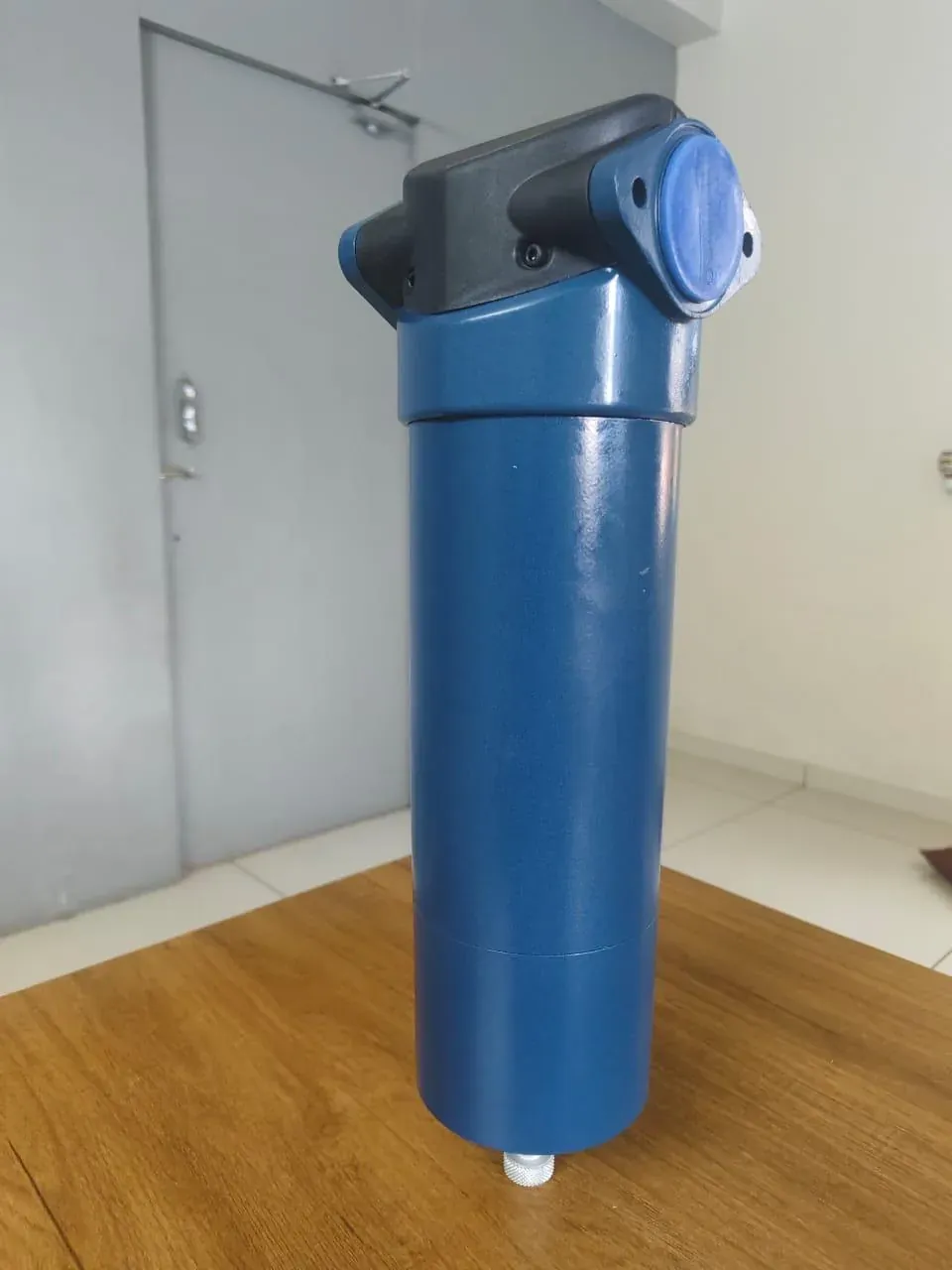
A new element starts with a low clean dP. As particles load the media, dP rises, slowly at first and then faster as the pores close. Coalescing filters behave a little differently: a new coalescing element “wets out” in its first hours of service and settles at a steady wet dP, which is its real working baseline. After that, a rise usually means particle loading, while a sudden jump often points to a liquid slug from a failed drain or an overloaded upstream separator.
Read dP sensibly:
- dP depends on flow. A reading taken at light load on a Sunday says little about the dP at peak production. Record it at normal full flow.
- dP depends on pressure. At lower line pressure the air is less dense, its velocity rises and so does dP for the same mass of air.
- A dP that never moves, or falls, is not good news. It can mean a torn element, a missing O-ring, an element not seated on its spigot, or a jammed gauge.
- Record the clean baseline after each element change. The trend from that baseline tells you far more than any single reading.
Typical differential-pressure values and change-out points
Exact values belong to each filter maker and element grade, so always check the housing data plate or element documentation. The figures below are typical of common industrial line filters operating at rated flow and around 7 bar, and are a useful sense check.
| Filter stage | Typical clean dP (dry or wet) | Typical change-out point | Usual replacement trigger |
|---|---|---|---|
| Water separator | Very low, often below 0.05 bar | No element; drain service only | Drain function, bowl condition |
| General-purpose coalescing | Around 0.1 to 0.2 bar wet | Around 0.35 to 0.7 bar, or as marked | dP limit or annual change |
| High-efficiency coalescing | Around 0.15 to 0.25 bar wet | Around 0.35 to 0.7 bar, or as marked | dP limit or annual change |
| Dust filter after desiccant dryer | Around 0.05 to 0.15 bar | Maker’s value | dP limit |
| Activated-carbon adsorber | Low and nearly constant | dP is not a useful guide | Hours, oil vapour or odour test |
The last row matters. A carbon element saturates without its dP changing, so it must be replaced on hours or on a measured result, never on a gauge reading.
Coalescing elements are also usually changed at least once a year even when dP is still low. The media’s ability to drain and hold oil degrades over time, and efficiency can fall well before the element looks blocked.
What a clogged filter really costs
The cost of a dirty filter is not the element; it is the electricity used to push air through it. When a filter’s dP rises from 0.2 bar to 0.8 bar, the point of use loses 0.6 bar. Operators then raise the compressor’s pressure setpoint to compensate, and the compressor works harder for every cubic metre it delivers.
A widely used rule of thumb for screw compressors is that each 1 bar of extra discharge pressure raises power by about 7%, and each 0.1 bar by roughly 0.7%. Higher pressure also increases leakage from every joint in the plant and raises unregulated consumption at end users.
You can estimate the burden yourself:
- Note the compressor’s average electrical input in kW (from the controller, an energy meter or a logging study).
- Find the excess dP across all filters compared with clean values, in bar.
- Multiply: kW × excess bar × 0.07 gives the approximate extra kW.
- Multiply by annual running hours and your tariff to get the yearly cost.
Repeat the sum for every filter in series. Three filters each carrying an extra 0.3 bar add up to almost a full bar. In most plants this yearly figure is larger than the price of a full set of elements, which is why the change decision should be driven by dP and energy, not by a wish to stretch the element.
Pressure losses from undersized housings are just as real. A filter selected for 600 m³/h on a line carrying 900 m³/h will show high dP even with a brand-new element. In that case the fix is a larger housing or a parallel pair, not more frequent element changes.
ISO 8573-1 air-quality classes and which filter gets you there
ISO 8573-1 defines purity classes for three contaminants: solid particles, water and total oil (aerosol, liquid and vapour). A specification is written as three numbers, for example Class 1.4.1 or Class 2.4.2. The filter train is then chosen to meet each number.
| Contaminant | Typical class targets | What usually achieves it |
|---|---|---|
| Solid particles | Class 1 to 3 for most industrial and process air | Coalescing or dust filters of the right grade, after the dryer |
| Water (pressure dew point) | Class 4 (+3 °C) or 5 (+7 °C) with a refrigerated dryer; Class 2 (−40 °C) or 3 (−20 °C) with a desiccant dryer | The dryer, not the filter |
| Total oil | Class 1 (≤0.01 mg/m³), Class 2 (≤0.1 mg/m³), Class 3 (≤1 mg/m³), Class 4 (≤5 mg/m³) | General plus high-efficiency coalescing; carbon adsorber for Class 1 |
A typical general-industry arrangement is a general-purpose coalescing filter before a refrigerated dryer and a high-efficiency coalescing filter after it. Food, pharmaceutical and electronics users frequently need a carbon stage or an oil-free compressor, and should confirm the result by measurement rather than by filter catalogue claims.
Remember that filter efficiency figures are quoted at rated conditions, often 20 °C inlet and a defined oil challenge. Hot inlet air in a Telangana summer carries more oil vapour, which coalescing filters cannot capture, so a filter that met Class 2 in winter may not in May.
Why filters fail early: symptoms and causes
| Symptom | Likely causes | What to check |
|---|---|---|
| dP rises within weeks of a change | Pipe scale after new piping work, rusting receiver, desiccant dust, high oil carryover from the compressor | Cut open the old element, inspect the receiver and upstream pipe, check compressor separator condition |
| Oil or water downstream despite a new element | Bypass past a damaged O-ring, element not seated, failed drain flooding the housing, dryer not working | Seal and seat condition, drain operation, dryer dew point |
| dP stays at zero | Torn media, missing element, blocked gauge ports | Open the housing, test the gauge |
| Element collapsed or burst | Wrong flow direction, liquid slug, pressure surge on start-up | Flow arrow, drain, start-up valve sequence |
| Carbon filter smells of oil quickly | No coalescing filter in front, wet air reaching carbon | Filter order, dryer performance |
A filter that keeps clogging is usually reporting a problem upstream. Treating it with more frequent element changes hides the cause and keeps the energy penalty.
How to decide when to change an element
- Record the clean dP at full flow after fitting a new element.
- Log dP weekly at a similar flow and pressure; a simple sheet beside the filter is enough.
- Change the element when dP reaches the maker’s marked value or the energy cost of the extra dP exceeds the element cost, whichever comes first.
- Change coalescing elements at least on the maker’s time interval, commonly annual, even if dP is low.
- Change carbon elements on hours or a measured oil-vapour result.
- After every change, check the O-ring, the seating, the flow arrow and the drain, then leak-test the housing under pressure.
- Note the new clean baseline and file the old element’s condition with the date.
Keep the drain in the plan. A float or electronic drain that sticks shut floods the bowl and saturates a coalescing element in hours. A drain that sticks open wastes air continuously.
Our routine filter checks on a service visit
- dP across each housing at load, compared with the last recorded baseline
- Gauge or sensor plausibility, including a zero check with the line isolated
- Housing size against actual peak flow and operating pressure
- Order of the stages and position relative to the dryer and receiver
- Drain function and condensate discharge route
- Element seating, O-rings, head and bowl condition, flow direction
- Upstream sources of contamination, including compressor oil carryover
- Total pressure loss from compressor discharge to the point of use
How Reddy Compressors helps
We have worked on compressed-air systems since 2002 from our base at Tarnaka, Secunderabad. As an independent multi-brand specialist we service filter trains on Atlas Copco, Ingersoll Rand, ELGi, KAESER, Chicago Pneumatic, Sullair and other installations, and on third-party filter housings. We are not an authorised distributor of these brands. We have tie-ups with all major and reputed brands.
Our service teams cover the whole of Telangana and Andhra Pradesh. We measure dP across your filters, trace the cause of short element life, check whether housings are sized for today’s flow, and identify replacement elements from the housing and old element so the fit is confirmed before we quote. Elements and spares are supplied across India. Where pressure loss looks significant, we can include the filters in a pressure-drop survey or wider air audit, and add element changes to a service plan or AMC.
What to send us
- Photos of each filter housing, its data plate and the element part number if visible
- Current dP readings and the compressor’s pressure setpoint
- Compressor make, model and dryer type
- Your air-quality requirement, if specified (for example ISO 8573-1 class)
- When elements were last changed and any symptoms you see
Frequently asked questions
When should I replace my compressed-air filter element?
Replace it when the differential-pressure gauge reaches the change-out value marked by the filter maker, or at the maker’s time interval, whichever comes first. Coalescing elements are typically changed at least once a year even if dP is still low, because their efficiency drops with age. Activated-carbon elements are replaced on hours or a measured result, since their pressure drop hardly changes as they saturate.
What is a normal pressure drop across a compressed-air filter?
A new coalescing element typically settles at around 0.1 to 0.25 bar once it has wetted out at rated flow, and dust filters are often lower. Most makers recommend a change at somewhere between 0.35 and 0.7 bar. Readings depend on actual flow and pressure, so compare your figure with the clean baseline taken at the same load rather than with a single published number.
How much energy does a clogged air filter waste?
The waste comes from the higher compressor pressure needed to overcome the blockage. A common rule of thumb is about 7% more compressor power for each extra bar of discharge pressure. Multiply your compressor’s average kW by the excess filter dP in bar and by 0.07, then by running hours and tariff, to estimate the yearly cost for each filter in series.
Why does my compressed-air filter clog so quickly?
Fast clogging usually means contamination is arriving from upstream. Common causes are rust and scale from new or old piping, a corroded receiver, desiccant dust from a dryer, or high oil carryover from a worn compressor separator. An undersized housing also shows high pressure drop from day one. Inspect the old element and trace the source rather than simply changing elements more often.
Does a coalescing filter remove moisture from compressed air?
It removes liquid water droplets and aerosols, but not water vapour. Air leaving a coalescing filter can still be saturated and will condense further downstream as it cools. To lower the pressure dew point you need a dryer, typically a refrigerated dryer for around +3 °C or a desiccant dryer for −20 °C or −40 °C. The filter protects the dryer and finishes the job afterwards.
Which filters do I need for ISO 8573-1 Class 1.4.1 air?
A typical arrangement is a general-purpose coalescing filter, a refrigerated dryer for Class 4 water, a high-efficiency coalescing filter for particles, and an activated-carbon adsorber to reach Class 1 total oil. Many users also add a final dust filter. Results depend on inlet temperature and compressor carryover, so the class should be confirmed by air-quality measurement at the point of use.
Related pages
Calculators and worked examples
These tools give indicative figures for screening, comparison and for preparing an enquiry. They run in your browser and send nothing. No prices or tariffs are assumed: enter your own to see costs. Efficiencies and other figures shown are example values: replace them with your own. Results are not a performance guarantee or a design certificate; final selection is confirmed by a service engineer against the machine data sheet and the site.
Pressure budget and the cost of excess pressure
Add up the pressure that is lost between the compressor and the point of use, and see what a lower set-point would be worth.
The worked example below shows the method with fixed numbers. Turn on JavaScript to change the inputs.
Worked example
Inputs
- Pressure needed at the point of use (bar g): 6
- Dryer and filter loss (bar): 0.5
- Piping loss (bar): 0.3
- Hose, fittings and regulator loss (bar): 0.3
- Control band and safety margin (bar): 0.3
- Current compressor set-point (bar g): 8
- Compressor input power (kW): 75
- Saving per bar reduced (%): 7
- Running hours per year: 6000
Result
- Total pressure losses: 1.1 bar
- Control band and safety margin: 0.3 bar
- Compressor pressure needed: 7.4 bar g (point of use + losses + band and margin)
- Possible reduction from current set-point: 0.6 bar
- Indicative energy saving: 18,900 kWh per year
- Indicative cost saving: Enter your electricity tariff (cost per kWh) above
Method. Required compressor pressure = point-of-use pressure + sum of losses. Savings = power × (reduction in bar) × saving per bar. A saving of roughly 6–8% of compressor power per bar of pressure is commonly quoted; it is indicative and varies with machine type and control, so edit it to suit.
What to take from it. The saving is real only if the farthest and most demanding point still works at the lower set-point. Prove it before you change the setting.
Technical content reviewed by D. Srinivas Reddy, Managing Partner and service engineer, Reddy Compressors. Last updated 17 October 2026. How our engineering content is reviewed.