
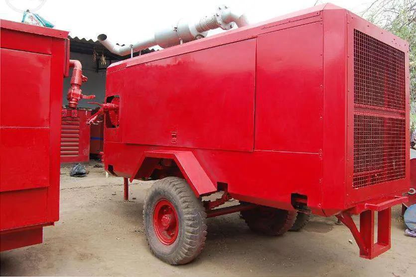
Reddy Compressors
Temporary instrument air must preserve the pneumatic service that the process needs, including pressure, flow, cleanliness and continuity at the instruments. Restoring header pressure alone does not demonstrate that control valves, positioners and other air-dependent equipment can perform their required functions. The temporary supply must be assessed together with the receiving network and the process operating state.
This guide supports maintenance teams, instrumentation engineers, operations personnel and project planners preparing for a planned or unplanned instrument-air outage. It explains demand assessment, air-quality requirements, temporary treatment, storage, tie-in boundaries, changeover verification and restoration. All calculations are hypothetical illustrations. They are not equipment selections, operating instructions for a particular plant or evidence of a completed project.
01 Define the outage and the required process state
Begin with the reason for the outage. A compressor failure, dryer failure, contaminated header, electrical interruption and planned receiver inspection create different temporary-supply boundaries. Identify which equipment remains available, which equipment is suspect and which part of the network can safely receive a new source. A temporary compressor connected upstream of a failed dryer may restore flow while leaving the original quality problem unresolved.
Operations must define the intended process state: continued production, reduced operation, controlled shutdown, maintenance hold or restart. Each state has its own valve movements, continuous air consumption and acceptable interruption. The required service during shutdown can differ substantially from the normal running average; several actuators may need to move together as part of the approved sequence.
Do not assume that keeping every valve energised is always the safest objective. Some functions are designed to respond to loss of air. The process owner and instrumentation team must establish the correct response and the role of the temporary supply. Adding air must not defeat an intended protective action or create an uncontrolled restart.
02 Map the users and their air dependencies
Prepare a register of the affected control valves, on-off valves, dampers, positioners, pneumatic controllers, analysers and other authorised consumers. Record equipment identity, supply-pressure range, air-quality requirement, normal consumption, movement demand and connection point. Distinguish a pneumatic actuator’s motive air from signal air and from any purge or analyser-support duty.
For each critical function, record the documented response to loss of supply, loss of signal and loss of electrical power. These are separate events. A spring-return actuator, double-acting actuator and assembly with a lock-up device may behave differently. The description “fail closed” should be verified against the installed assembly and cause-and-effect documentation, not inferred from the valve’s service name.
Identify local regulators, boosters, accumulators, non-return valves and restrictions between the header and the actuator. Their condition and configuration influence response time and usable reserve. A header drawing that omits these accessories can conceal the actual limiting point. Use the installed arrangement as the basis for temporary support and retain unresolved discrepancies for the responsible engineer.
03 Establish a measurable service specification
The specification should define minimum and maximum pressure at the agreed delivery point, normal and peak reference-air flow, allowable quality limits, operating duration and continuity requirements. State the reference conditions for airflow and the pressure basis for dew-point measurements. Assign a delivery boundary that can be measured and inspected, such as the temporary connection immediately before the receiving instrument-air header.
Separate project requirements from equipment capability. A rental package’s published pressure or nominal dryer class does not automatically become the plant’s acceptance criterion. The receiving instruments and process requirements determine what is needed; the proposed package must then demonstrate that it can deliver that service under the specified site conditions.
Requirement | Information to define | Evidence for acceptance |
|---|---|---|
Pressure | Minimum operating and maximum permitted values at stated points | Measurements during agreed demand scenarios |
Flow | Continuous use, event demand and reference conditions | Demand assessment and verified net package capacity |
Moisture | Pressure dew point and measurement pressure | Suitable measurement at the agreed delivery point |
Contamination | Particle and oil requirements plus any special contaminants | Appropriate sampling, test records and equipment evidence |
Continuity | Required process state and tolerable supply interruption | Reviewed failure response and demonstrated support arrangement |
Where a site specification invokes an instrument-air or compressed-air quality standard, identify the applicable edition and numerical requirements in the project record. Avoid claiming compliance from a generic description such as clean, dry air. The ISA catalogue identifies ISA-7.0.01 as an instrument-air quality standard; this guide does not reproduce its requirements or substitute for the controlled project copy.
04 Measure the continuous demand before adding event loads
Continuous demand may include positioner consumption, pneumatic controller bleed, analyser purges and leakage. Some devices consume very little in a steady state but need appreciably more during movement. Obtain manufacturer data for the installed models and compare the resulting estimate with flow measurements where a suitable meter exists.
Use representative operating periods. A quiet maintenance window can understate normal demand, while a period with temporary hoses or unrelated users connected can overstate the essential instrument load. Document which users were active and the condition of isolation boundaries during measurement. A reading without this context is difficult to use for either sizing or later comparison.
Investigate leakage where it can be addressed without disturbing the process. Include remaining unavoidable demand explicitly rather than burying it inside a large contingency percentage. Do not isolate a suspected leaking branch until its function is identified and the responsible operations team authorises the action. A small pneumatic line may serve a consequential control function.
05 Convert actuator movement into reference air
Actuator air demand depends on chamber volume, supply pressure, movement sequence, cycling frequency and accessory behaviour. Use manufacturer consumption data for the complete assembly wherever available. Confirm whether the stated figure is per stroke, per full cycle or per unit time, and whether it already includes the pressure conversion to free or reference air.
For an illustrative screening calculation, suppose a chamber’s effective filled volume is 8 litres and its final pressure is 7 bara. At a 1 bara reference and equal temperature, the contained air corresponds to 8 × 7 ÷ 1 = 56 reference litres. This is an approximate filled-volume relationship, not a universal inlet-consumption formula. Initial air, changing chamber geometry, dead volume and the actual exhaust sequence affect consumption.
For a double-acting assembly, opening and closing may pressurise different effective volumes. Do not automatically double one chamber value where the geometry differs. Add positioner, booster and other relevant consumption on a compatible basis. For final selection, obtain validated event-consumption data or measurements and confirm that the delivery path can supply the required instantaneous flow.
06 Assess simultaneous movements and restart demand
Demand should cover credible operating events, including coordinated valve movement, process transitions and restart after an outage. Averaging a short event over an hour can hide the flow needed over seconds. Conversely, adding every installed actuator at full consumption may produce an unrealistic selection if the reviewed process sequence prevents that combination.
Assume a verified continuous demand of 0.80 m³/min on a common reference basis. For illustration, a reviewed event moves twelve assemblies, each requiring 0.060 reference m³ during the event. Total event volume is 0.72 m³. If it is delivered over 10 seconds, the average event contribution over that interval is 0.72 × 60 ÷ 10 = 4.32 m³/min. Combined demand averages 5.12 m³/min during the interval.
The event’s instantaneous peak can exceed that average. Instrument tubing, boosters and local storage can determine whether the required stroke time is met. Do not slow or stagger a protective sequence merely to fit a smaller compressor. Any change in valve timing or process sequence belongs to the plant’s engineering and operating review, not an informal rental-sizing adjustment.
07 Size the complete temporary package on net flow
Distinguish compressor delivery from air available after drying, regeneration and auxiliaries. Include actual treatment consumption at the operating condition. Some dryers consume a proportion of compressed air; others have different regeneration demands and electrical dependencies. Select from supplier data for the specific dryer and control mode rather than applying one purge percentage to every package.
If the continuous net requirement is 0.80 m³/min and an illustrative dryer consumes 15% of gross flow, gross delivery must be at least 0.80 ÷ 0.85 = 0.941 m³/min to balance that continuous demand. If the temporary package instead delivers 2.0 m³/min gross under the relevant conditions, its assumed net output is 1.70 m³/min. The remaining 0.90 m³/min can recharge storage only while other demand stays at 0.80 m³/min.
This package would not directly cover the 5.12 m³/min event average in Section 06. Storage or a different verified supply arrangement would be needed. Check compressor capacity at required pressure and site conditions, dryer correction factors, filtration losses and the ability to operate stably at low load. A large catalogue flow number does not resolve short-duration response or quality.
08 Calculate storage for the actual pressure window
Usable storage is the air available between the initial receiver pressure and the lowest pressure that still supports the downstream service. The receiver’s physical volume alone does not establish ride-through time. Include downstream losses, regulator behaviour and minimum actuator supply requirements when choosing the lower pressure boundary.
Using the hypothetical event above, net demand exceeds the 1.70 m³/min supply by 5.12 − 1.70 = 3.42 m³/min for 10 seconds. The reference-volume deficit is 3.42 × 10 ÷ 60 = 0.57 m³. Under an ideal-gas, equal-temperature approximation, a receiver dropping from 8.5 bara to 7.5 bara at a 1 bara reference would need 0.57 × 1 ÷ (8.5 − 7.5) = 0.57 m³ of physical volume to match that simplified balance.
This is not a final receiver size. Real temperature change, flow restrictions, pressure response and event shape require assessment. At the assumed 0.90 m³/min recharge surplus, replacing 0.57 m³ takes at least 0.633 minutes, approximately 38 seconds. Repeated events arriving before recovery can deplete the reserve. Confirm any pressure-vessel and installation requirements through the project’s responsible personnel.
09 Distinguish event buffering from outage reserve
Storage that smooths an actuator event may provide little protection against a complete loss of compressor delivery. Calculate the loss-of-supply case separately, with the required process actions included. Identify whether the reserve must support normal control, a transition to a defined state or a specified number of actuator movements.
For illustration, a 1.0 m³ receiver with a usable 1.0 bar pressure difference and a 1 bara reference contains approximately 1.0 reference m³ of usable air under the same simplified temperature assumption. At a continuous demand of 0.80 m³/min, the theoretical no-event duration is 1.25 minutes, or 75 seconds. This is not 75 seconds of guaranteed plant protection.
If an additional event consumes 0.72 reference m³ during that interval, only 0.28 m³ remains for the assumed continuous load, equivalent to 21 seconds on the simplified balance. Timing and local pressure response still matter. Compare the complete demand trajectory with detection, decision and protective-action times rather than assigning a reassuring autonomy figure from receiver volume alone.
10 Preserve air quality through the whole delivery route
Air quality must be suitable at the receiving system, not only at the compressor outlet. Temporary hoses, wet receivers, dirty manifolds and an existing contaminated header can compromise an otherwise suitable package. Identify the condition and previous service of all components that contact the delivered air and protect open connections during storage and mobilisation.
Specify particle, water and oil requirements separately, together with any process-specific contaminants. Oil-free compression does not by itself establish moisture or particle performance, nor does it prove that the downstream route is uncontaminated. Conversely, a filtration label without evidence of the complete treatment arrangement does not establish suitability for sensitive instruments.
Manufacturer requirements remain important. Emerson’s safety guidance identifies unsuitable instrument-air cleanliness and dryness as a potential cause of uncontrolled process behaviour and directs users to appropriate equipment and filtration guidance. That supports checking the actual installed instruments rather than applying one generic filter specification to all of them.
11 Specify dew point at the relevant pressure
Pressure dew point describes the temperature at which water begins to condense at a stated pressure. Atmospheric dew point after sample expansion is not interchangeable with pressure dew point in the operating header. Record sample pressure, measurement method and any conversion used so that results can be compared with the project requirement.
Evaluate the coldest credible downstream condition, including outdoor tubing, night-time exposure and cooled process areas. A dryer that prevents liquid water in a warm compressor enclosure may not prevent condensation in a colder section. The required dew-point target and margin must come from the applicable site and equipment specification, supported by the environmental assessment.
For illustration only, if the project requires a pressure dew point no warmer than −40°C at its defined sampling pressure, a reading of −20°C does not meet that requirement simply because both values are below freezing. The −40°C figure is an assumed project criterion, not a universal rule for every instrument-air application. Assess sensor condition and sampling suitability before accepting the result.
12 Select treatment for operating and recovery conditions
Check the dryer and filters at maximum relevant inlet temperature, minimum operating pressure and required flow. Confirm the supplier’s correction-factor convention before applying it. If an illustrative nominal dryer rating is 3.0 m³/min and the applicable combined capacity multiplier is 0.70, corrected capacity is 2.1 m³/min. That simple calculation is valid only if the supplier defines the factor as a multiplier on nominal capacity.
Dryer readiness after transport, storage or maintenance needs attention. A cold start, wet desiccant or regeneration interruption can affect initial performance. Establish how the package reaches the required delivery quality before connecting it to the sensitive system, including appropriate measurement and controlled discharge arrangements. Do not use the instrument header as a convenient place to clear moisture from an unproven temporary line.
Provide suitable downstream particle control where the treatment technology requires it. Plan drain operation, filter condition monitoring and maintenance without an uncontrolled quality interruption. Treatment bypasses must not silently become normal service. Their effect on air quality and process operation must be assessed before any use.
13 Choose the tie in boundary deliberately
The connection should supply the intended users while preventing unwanted backfeeding into failed or contaminated equipment. Review the actual piping and instrumentation drawing and verify the physical installation. Determine isolation, non-return protection, pressure regulation, relief requirements and sampling points through the responsible engineering team.
Distinguish a connection to a healthy downstream header from a connection to an uncertain network. If the original outage involved contamination, feeding clean air into the same header does not prove the contamination has been removed. Assess whether affected sections require cleaning, component attention or further testing before restoration of their function.
The temporary connection must be mechanically and chemically suitable for its service. Confirm ratings, cleanliness, routing, support and protection from site damage. Identify trapped-pressure sections and the method for verified isolation before work. This guide deliberately provides no universal valve-opening sequence: the correct order depends on the installed arrangement and the reviewed plant procedure.
14 Define the pressure budget and control arrangement
Work backward from the limiting instrument or local regulator inlet. Include pressure loss through temporary treatment, distribution, tie-in components and the relevant permanent branch. Check both minimum pressure during movement and maximum pressure at low demand. A stable main-header reading can coexist with inadequate pressure at a remote actuator during a fast stroke.
Suppose a local assembly requires at least 5.5 barg at its agreed supply point. Assumed losses are 0.25 bar through treatment, 0.30 bar through the temporary route and 0.20 bar through the relevant permanent branch. The upstream requirement is 6.25 barg before accounting for compressor control variation and regulator performance. This is a hypothetical budget, not an authorised setpoint.
Where temporary and permanent sources operate together, review pressure-control interaction and permitted parallel operation. Avoid repeated loading and unloading, unintended reverse flow or a supply pressure above downstream limits. Identify which source controls the operating band, what starts the standby source and what happens if a regulator or control signal fails.
15 Assess common failures and standby readiness
Redundancy must cover the service chain. Two compressors feeding one dryer, one vulnerable hose or one electrical source may still have a single failure that removes acceptable instrument air. Assess the compressor, treatment, power or fuel, control system, distribution and connection together when deciding what continuity the package provides.
Failure scenario | Question for the project team | Required response definition |
|---|---|---|
Running compressor stops | Can the remaining source support essential demand | Start or transfer timing and usable reserve |
Dryer loses performance | Is pressure still present but quality unacceptable | Quality alarm response and approved alternative |
Temporary main is damaged | Are local reserves and isolation effective | Defined process response and repair boundary |
Shared electrical source fails | Which compressors, dryers and instruments lose power | Independent support or controlled process transition |
Quality instrument fails | Can service quality still be demonstrated | Verification method and operating decision |
Standby availability includes compatible connections, readiness of treatment and an established operating method. A cold or unverified spare is not equivalent to a proven online alternative. State the demonstrated restoration time and remaining uncertainties. Do not claim uninterrupted service merely because the equipment list contains two compressors.
16 Monitor pressure and quality with actionable alarms
Select monitoring points that reveal the condition relevant to the process. Header pressure, the limiting branch pressure, dew point, filter differential pressure and package status may all be useful, but they answer different questions. A dryer alarm and a low-header-pressure alarm should not be treated as interchangeable indicators of acceptable air.
Define alarm thresholds, delay, recipients and required actions through the site’s operating and instrumentation review. Consider the interval between detection and loss of the required function. A slow sample response or an unattended local alarm can consume much of the available reserve. Confirm that the alarm is visible to the person expected to act during every supported shift.
Use time-synchronised records when comparing valve movement, pressure dips and compressor response. Record sensor identity and verification status. Portable logging can support diagnosis, but it does not automatically become a protective function. Any credited safety function, override or change to existing protection needs the plant’s established engineering process; a temporary rental arrangement does not justify bypassing it.
17 Verify the supply before controlled changeover
Acceptance should establish both service quality and operating behaviour. Check the installed configuration against the agreed drawing and scope. Verify package identities, ratings, treatment readiness, cleanliness, isolation boundaries, monitoring, utilities and responsible personnel. Confirm that the process is in the state required by the approved changeover plan.
Demonstrate the specified pressure and quality at the delivery boundary before exposing the receiving system where the arrangement permits. Exercise representative demand through an approved test method. Live valve movement can affect the process; perform it only within an authorised operational or test window. A successful no-load pressure check is insufficient evidence for the transient duty.
During the controlled transfer, record the relevant pressure and quality trends and confirm the intended response at the agreed users. Establish explicit conditions for stopping the transfer or reverting to the approved alternative. The plant team owns the process decision. Rental personnel should not independently alter interlocks, valve failure behaviour or operating limits to complete a connection.
18 Operate through uncertain repair duration
An outage initially expected to last one shift can extend through diagnosis, parts delivery and recommissioning. Plan the temporary supply for the credible duration range, including service access, fuel or electricity, consumables, dryer operation, monitoring and personnel cover. Extension planning should occur before a maintenance interval or fuel constraint becomes urgent.
Keep a shift record of pressures, dew point where required, alarms, operating hours, maintenance and changes in process demand. Record any additional consumer connected to the temporary header. A small construction or cleaning load can be significant beside a modest instrument-air base load and can compromise the carefully assessed reserve.
Diagnose pressure and quality deviations separately. A pressure dip associated with a valve event may indicate a transient limitation; increasing dew point at stable pressure points to another issue. Apply the approved response rather than masking one problem with another adjustment. Changes in setting, treatment mode or connection require review against the agreed service specification.
19 Restore permanent service and evaluate the outcome
Repair completion is not proof that the permanent system is ready to resume the instrument duty. Verify the repaired equipment, treatment performance, controls and downstream condition relevant to the original failure. Where contamination occurred, include the affected network and instruments in the recovery assessment. A repaired compressor cannot remove contamination already deposited downstream.
Use a reviewed transfer-back plan and confirm stable service before releasing the temporary package. Record the permanent system’s accepted condition, the timing of disconnection and the return of temporary isolation or control arrangements to their intended state. Retain the temporary supply for any agreed observation period rather than demobilising solely because the repaired machine has started.
Evaluate the support arrangement using measured service and the defined project objective. As an illustrative commercial comparison, Package A at ₹20,000 per day for six days plus ₹80,000 mobilisation totals ₹200,000. Package B at ₹27,000 per day plus ₹50,000 mobilisation totals ₹212,000. The ₹12,000 difference says nothing by itself about required quality or continuity; compare only arrangements that satisfy the same duty. Do not claim avoided production loss without evidence of the credible alternative outcome.
For an enquiry, provide the affected process state, instrument register, demand evidence, pressure and quality specification, outage duration, tie-in drawing and utilities. Reddy Compressors can assess project requirements for Hyderabad, Secunderabad, Telangana, Andhra Pradesh and other requested locations subject to configuration and support confirmation. Availability, treatment capability and mobilisation timing must be established for the actual project.
20 Frequently asked questions
Can a normal rental compressor replace instrument air
Only as part of a verified arrangement that meets the receiving system’s pressure, flow, quality and continuity requirements. The compressor alone is not the complete supply. Drying, filtration, distribution cleanliness, monitoring and process compatibility must be included. Do not connect an ordinary tool-air package to a sensitive instrument header on pressure rating alone.
Does oil free compression guarantee instrument air quality
No. It does not establish the required moisture level, particle condition or cleanliness of temporary and permanent downstream equipment. Define measurable quality requirements at a stated delivery point and verify the complete system against them. Manufacturer certification for one component should be interpreted within its actual scope.
Why can header pressure look normal while valves respond slowly
Flow restrictions, local regulator behaviour, small tubing, accessory faults or inadequate local reserve can limit air delivery during movement. The main header gauge may miss a short or remote pressure dip. Compare time-aligned pressure measurements and the actual valve event using a test method that is safe for the process.
How much receiver capacity is needed for an outage
There is no universal volume. Calculate the required reference-air quantity over the defined event or loss-of-supply period, then assess the usable pressure window and downstream response. Include continuous consumption, valve movements and recharge opportunities. A receiver selected only from average consumption may provide inadequate reserve for a coordinated transition.
Can nitrogen be used when instrument air is unavailable
It must not be treated as an automatic substitute. The installed equipment, process, exhaust locations, ventilation, material compatibility and supply arrangement require specific engineering review. Nitrogen can displace oxygen, and not every pneumatic assembly or application is approved for another gas. This page’s air calculations and connection discussion do not authorise such a substitution.
Can production restart as soon as pressure returns
Pressure recovery is only one condition. Confirm the required air quality, instrument and valve condition, process state, controls and approved restart requirements. Restoring air can cause movement in some assemblies. Operations and instrumentation personnel must manage restart through the plant’s procedure rather than treating a normal gauge reading as permission to resume production.
Sources and evidence basis
22 Sources and engineering provenance
[S1] User-supplied 13-B.A.-21-7-26-RC-2.pdf, compressed-air treatment discussion. Reviewed passages address instrument-air reliability, measurable contamination requirements, pressure dew point and downstream temperature. These principles informed the quality and treatment sections without reproducing the general treatment article.
[S2] User-supplied 04-B.A.-16-8-26-RC-2.pdf, rental planning and compressed-air system engineering. Previously reviewed material establishes planned temporary supply, connection readiness and shared-dependency considerations.
[S3] International Society of Automation, public catalogue entry for ISA-7.0.01-1996, Quality Standard for Instrument Air. Used only to identify the standard; its full requirements were not consulted or reproduced. The project team must use the applicable controlled specification. https://www.isa.org/products/isa-7-0-01-1996-quality-standard-for-instrument-ai
[S4] Emerson, Safety Instructions, D103022X0GB, May 2026, instruments, switches and accessories. Primary manufacturer guidance on suitable instrument-air supply and equipment-specific filtration decisions. No model-specific limit is generalised to all instruments. https://www.emerson.com/is/content/emerson/en/final-control/flow-controls/documents/d103022x0gb.pdf
All numerical flows, actuator-event volumes, purge fractions, receiver pressures, treatment factors and costs in this page are assumed for illustration. Storage calculations use explicitly simplified ideal-gas balances and are not final pressure-vessel selections. Actual valve response, safety-function performance, compliance and project savings require appropriate project evidence.