
Interactive resource
Use the working tool for this page
This page has a matching worksheet, calculator or comparison resource. It runs in your browser: enter your own measured values and keep the evidence behind every result.
Open resourceVersion: 1.0.0. Issue date: 07 October 2026.
1. Engineering answer: deliver the required air at the working breaker
A pneumatic breaker needs its documented operating pressure and airflow at the tool inlet while it is breaking material. The compressor's advertised capacity, receiver size or stationary gauge reading cannot establish that condition alone. Match the exact breaker and working pattern to the delivered compressor capacity, complete hose route, preparation equipment, manifold and other simultaneous users. Then verify the service at the actual workfront. [S1, S2; N1]
The useful selection is a complete air-service arrangement, not a compressor-to-breaker ratio. A single breaker on a long restricted hose can underperform even with spare compressor capacity. Several breakers on a well-designed common supply can still overwhelm the source during sustained overlap. These are different failure mechanisms and require different corrections. Increasing source pressure without identifying the limiting part can expose components to an unsuitable condition without solving the underlying problem.
This page owns the breaker duty and hose schedule. It joins model-specific consumption, working duration, concurrency, dynamic pressure, physical connections and workfront changes in one reviewable record. It does not provide a universal instruction that one nominal compressor size operates a fixed number of jackhammers. Such a statement would omit the equipment variants, operating pressure, auxiliary users, site conditions and acceptable performance.
Begin with the required result: the identified material-removal task completed within the permitted working arrangements. Keep air-service performance separate from structural demolition approval, buried-service clearance, dust control, operator exposure and equipment condition. Satisfactory airflow does not authorise an unsafe task, and poor progress does not prove that more airflow is required. The breaker, insertion tool, material, operator method and supporting controls remain part of the application.
For an existing complaint, compare the compressor outlet, distribution branch and tool inlet during the same event. Preserve whether the breaker was actually operating against material, which other users were active, and how long the event lasted. An observation taken after the trigger is released may describe recovery rather than the pressure available during useful work.
2. Identify the equipment before applying a demand value
The subject is a compressed-air-powered, handheld percussion breaker used for a documented breaking duty. It is not an electrical circuit breaker, a hydraulically powered excavator attachment or a petrol-driven tool. The shared word breaker does not make their supply requirements interchangeable. A hydraulic attachment may have a separate compressed-air interface for a special purpose, but that is not the motive-air duty considered here. [N1]
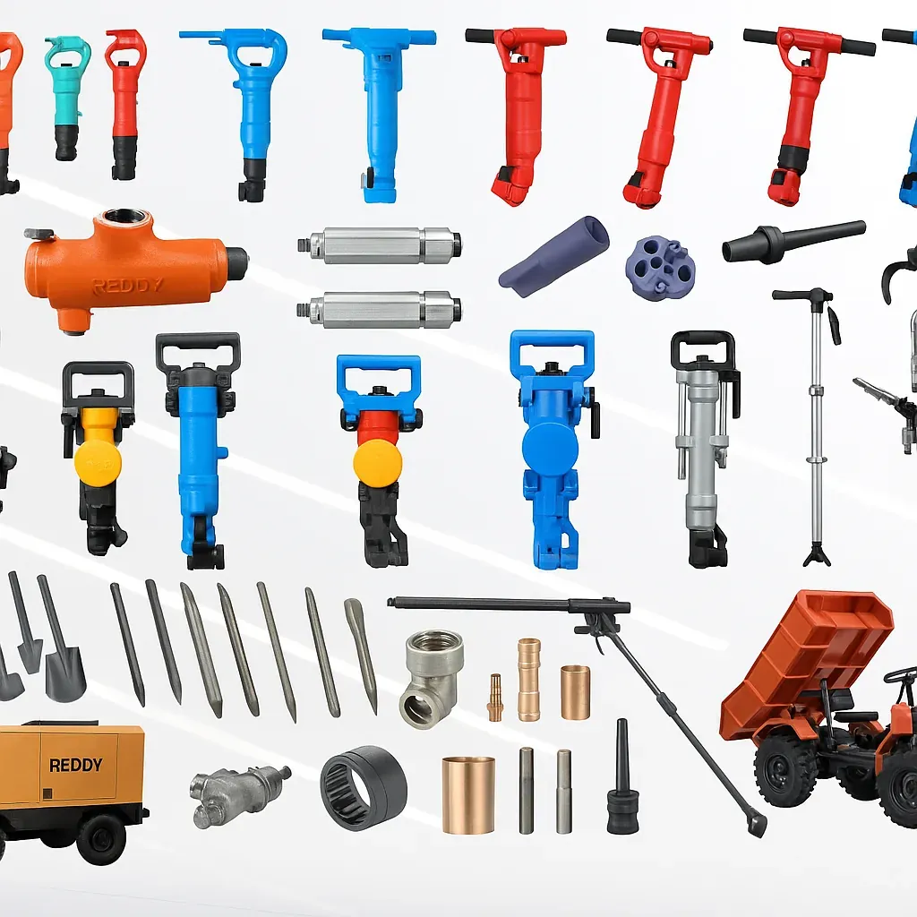
Record manufacturer, exact model, serial or asset identity, variant, inlet connection, insertion-tool shank and relevant manual revision. Distinguish silenced and vibration-reduced variants where the manufacturer identifies them. Product families may contain several shank arrangements or other configuration differences; a broad name copied from a hire quotation can be insufficient to establish the delivered equipment.
Record the tool's documented consumption with its pressure and reporting basis. Also record maximum permitted inlet pressure separately from a recommended or rated working pressure. A catalogue operating point is not automatically an instruction to set every outlet to that pressure, and the numerical value of an inlet connection does not establish minimum hose internal diameter. [R1–R3; N1]
The work record should distinguish the breaker body from the insertion tool, often called the steel, point or chisel. Tool retention, shank fit and intended material remain relevant to the outcome, but do not infer safe interchangeability from a similar appearance. An air-supply review should flag a missing identity rather than fill it with the nearest catalogue model.
For a rental fleet, preserve the actual dispatch and replacement identities. A substitute with a different consumption can change the source and hose requirements even when it is described as the same weight class. The schedule should survive a change of shift: another person must be able to identify the tool, its approved connection route and the assumptions behind the air-service arrangement without relying on an informal conversation.
3. Translate the workfront into a duty specification
Describe the material and task at the level needed to select equipment and assess output: asphalt removal, concrete breakout, masonry work or another permitted application. Record thickness or depth where known, reinforcement or inclusions, access, working orientation, available support, expected fragment handling and the required completion window. The responsible construction team must establish structural and utility-clearance requirements independently of this air calculation. [N1]
Separate available shift time, active breaking time, repositioning, clearing, waiting, inspection and equipment changes. A breaker can operate nearly continuously during a working burst even if its total trigger-on time is modest across the day. That sustained burst is the relevant source-capacity case; the entire shift average is a different consumption metric. Preserve the duration of both.
List the other services required while breaking occurs. A pneumatic dust extractor, air-driven auxiliary pump, additional hand tool or other confirmed user belongs in the concurrent demand. A water-spray system may instead require a water or electrical supply. Identify its actual energy source rather than adding a guessed pneumatic allowance merely because it supports a pneumatic tool.
State where the work starts and how it moves. A compact first-day layout may become a long common trunk feeding several remote branches. Crossing protection, access restrictions and relocation can dictate a hose route longer than the straight-line distance. The design route is the installed path, including usable slack and connections, not the distance measured on a sketch.
Define an acceptable output measure and its boundary. Area cleared at a stated thickness, verified in-place material volume or another agreed quantity can support a later comparison. Loose rubble volume and original solid volume are not automatically interchangeable. A claim of faster breaking also needs comparable material and task conditions; one favourable demonstration should not silently become the guaranteed productivity of the equipment.
4. Read manufacturer consumption without turning it into a universal chart
Manufacturer records show why exact identification matters. The following official Chicago Pneumatic US product listings each label consumption at 90 psi, while listing the same nominal 3/4-inch NPT air inlet. They are source-reading examples, not recommendations for a customer's tool or an assertion of local stock. [R1–R3]

Identified manufacturer listing | Published air consumption at 90 psi | Published air inlet | Permitted conclusion |
|---|---|---|---|
CP 1210 | 48 CFM | 3/4-inch NPT | Use the identified listing and configuration; confirm the complete flow reference basis. |
CP 1260 | 63 CFM | 3/4-inch NPT | Equal inlet thread does not establish equal consumption. |
CP 1290 | 81 CFM | 3/4-inch NPT | A larger consumption requires its own duty and connection assessment. |
The table does not establish the full inlet reference temperature, humidity convention or performance at a different pressure. Those details remain clarification items before comparing a manufacturer's CFM with a compressor's free-air-delivery record. The cited web listings are not a replacement for the operating instructions supplied with the exact equipment.
A pure conversion is reproducible: one cubic foot per minute equals 0.028316846592 cubic metres per minute; one litre per second equals 0.06 cubic metres per minute. These relationships change units, not the physical definition. Converting 63 CFM to approximately 1.784 m³/min does not establish that this is actual compressed volume inside the hose or predict operation at a new pressure. [S1; N2]
Do not divide every listed breaker consumption by an assumed duty factor, and do not assume that a manufacturer's word average always means the same thing. Establish whether the value represents operation, a defined load condition, a complete cycle or a specified time average. A consumption value can be accurate yet unsuitable for the calculation in which it has been placed.
When evidence conflicts, retain both records with their source, date, unit and model configuration. Resolve the discrepancy before issuing a final selection. Different regions, variants, test conditions or publication revisions can explain a mismatch. Quietly choosing the smaller number to fit an available compressor removes the very uncertainty the engineering schedule should expose.
5. Keep working pressure, minimum service pressure and pressure limits separate
The pressure requirement has several distinct parts. The manufacturer's operating instructions define the permitted conditions. The project defines the required performance within those conditions. The selected compressor and regulation arrangement must support that service without exceeding any component's allowable pressure. A maximum-pressure number is a limit, not a desirable operating target. [S2; R5]
Record pressure at named locations: compressor service outlet, common trunk inlet, manifold, preparation inlet and outlet, and breaker inlet. Gauge pressure is appropriate for a compatible pressure-drop comparison, but absolute pressure is required for gas-inventory and gas-state ratios. Preserve the local atmospheric reference when converting between them; do not use a gauge pressure directly in a pressure ratio.
A static gauge generally reports a condition with little or no tool flow. Once the breaker operates, the hose, couplings, preparation and common supply can create additional pressure differences. An acceptable no-flow setting therefore does not establish an acceptable working inlet pressure. An instrument also needs sufficient response for the question; a slow display may conceal short disturbances.
For a supported regulator outlet value, the endpoint screening relation is p_tool = p_reg,out − sum of downstream passive losses. The regulator itself must be assessed at its actual inlet condition and demand. Do not subtract intentional regulation and droop again from an outlet pressure that already represents the flowing condition. Do not add unrelated worst-case observations and label them a measured event.
Also review the no-demand and recovery conditions. A changed regulator setting or configuration should not create excessive pressure when tools stop. Components upstream and downstream may see different maximum conditions. A larger-capacity source must not bypass a necessary pressure-control or protective function simply because its nominal discharge pressure appears familiar.
6. Distinguish active consumption from the shift average
For one explicit constant-flow active state and an explicit inactive state, mean reference flow is q_mean = u × q_active + (1 − u) × q_inactive. Here u is the fraction of the declared time window spent active. The equation describes a teaching model; real consumption may vary within the active period and should use measured or supported state data where that variation matters. [S1; N2]
For several nonoverlapping states, V_ref = sum(q_j × t_j), with flow and time in compatible units. Using m³/min and seconds requires division by 60. A mean is the integrated volume divided by its defined time window. Include the off-state term when the reporting boundary contains a leaking hose, continuously supplied auxiliary or another legitimate idle load; do not assume it is zero merely because the breaker trigger is released.
Three time scales deserve separate treatment: the tool's internal percussion, the operator's sustained breaking burst, and the workfront or shift schedule. A source may support the daily mean while failing during a long burst. A hose may support a mean over a minute while imposing an unacceptable inlet-pressure drop during the active interval. Neither issue is resolved by a more precise daily total.
Do not calculate flow from blows per minute alone. Impact frequency does not define swept gas volume, internal losses, exhaust behaviour or the manufacturer's consumption boundary. Likewise, multiplication of a published impact energy by blow frequency gives a particular mechanical-rate interpretation only when those quantities are applicable; it does not supply compressor airflow or electricity consumption.
A useful register keeps the original source value, its meaning, the selected working state, elapsed time and the calculation performed. This makes double averaging visible. A measured branch mean already containing inactive intervals should not be multiplied by a utilization fraction from the same period a second time.
7. Construct the simultaneous breaker schedule
For a shared supply, calculate the compatible flows actually active at each time. A site with three breakers is not automatically a three-breaker simultaneous duty, but a smaller concurrency needs evidence: the work method, enforced operating arrangement or relevant observation. Staffing alone may not establish the maximum combination if another crew, spare tool or auxiliary can connect to the same manifold.
Use an event schedule with asset identity, workfront, start, finish and flow definition. For constant-rate examples, adopt half-open intervals [start, finish): one event ending exactly when another begins does not create a positive-duration overlap. Preserve the chronological intervals so that the peak magnitude, peak duration and recovery opportunity remain visible. A sorted demand-duration curve cannot reconstruct the original sequence.
For unlike tools, a simultaneous count is incomplete. Two heavy breakers and one smaller tool can demand more air than three smaller tools. Identify the actual combination. Add auxiliaries only once and locate them correctly: a compressor-room dryer purge upstream of the measured net service boundary should not be added again if it is already excluded from the stated delivery.
Coincidence should be explicitly defined rather than stored as a bare diversity number. Where a ratio is used, state its numerator, denominator, consumer set and time basis. A mean-duty fraction, a peak coincidence ratio and a reserve provision answer different questions.
Test the credible cases: normal operation, maximum permitted overlap, startup after a pause, a relocated workfront, a shared auxiliary demand and an equipment substitution. A measured day without overlap proves only that observed pattern. Conversely, a theoretically possible combination need not become continuous design duty when its duration and control constraints are documented. Keep the consequence and evidence attached to each case.
8. Compare net delivered compressor capacity at the correct condition
Compare the requirement with documented delivered air at the operating pressure and site conditions, not with compressor motor power or a model name containing a convenient CFM number. Record whether the supplied capacity is at the package outlet, after optional treatment, at the job manifold or on another boundary. Capacity, reference state and pressure must describe the same performance point. [S1; N1]
For a portable compressor, request the manufacturer's applicable site-performance information for altitude, ambient temperature, inlet condition, available pressure range and any treatment option. A gas-law conversion of a quoted volume is not an engine or compressor derating model. This page provides no universal percentage deduction for hot weather or elevation and does not assume every portable package responds identically.
Separate gross package delivery from net air available to the workfront. Internal uses, connected treatment and other branches may already be included or excluded from the quoted number. Create a boundary sketch and subtract only the loads genuinely inside the comparison. If both package and downstream measurements are available, align their timestamps and account for storage changes before interpreting their difference as loss.
Source response also matters. The time required to load, recover pressure or return from an idle state can influence a short event even when rated delivery is sufficient once established. Record the selected package's permitted control behaviour. Do not improvise control changes or defeat a protective feature to obtain faster response.
A source-capacity pass is only one status. Retain separate hose/pressure, air-quality, connection-integrity, operating-duty and site-readiness statuses. A compressor capable of the required flow is not proof that the temporary hose installation can carry it. A pressure-stable demonstration is not proof of adequate delivery throughout an entire repeating campaign.
9. Engineer the common trunk and individual branches together
Represent the supply as actual segments: source outlet, treatment, trunk, manifold, branch equipment, flexible tail and breaker. Identify each branch and shared element. The common trunk carries the simultaneous total; the final tail generally carries its own tool's active flow. Applying a single-tool loss to the common trunk can understate the pressure drop precisely when several users operate together. [N1 extending S1, S2]
The manifold should have a documented pressure rating, suitable connections, required isolation and sufficient flow performance for the intended combinations. Outlet count is not capacity. A manifold with four connections does not establish that all four can serve high-demand tools at the necessary pressure, and a reducer at its inlet can become a shared restriction.
Record where regulation and lubrication occur. One common regulator may be suitable for a documented group, while other configurations need separate pressure zones. A common lubricator must not contaminate an oil-sensitive auxiliary. Branch identity, preparation and the permitted connected equipment should be visible in the hose schedule, not left to operators to infer from thread size.
Consider access to controlled isolation and pressure verification without requiring personnel to enter the breaking area. Moving a manifold closer to the work can shorten individual tails, but it also changes exposure to debris, traffic, water and impact. Evaluate the whole arrangement rather than treating minimum hose length as the only objective.
For multiple sources, interconnections need a deliberately engineered arrangement. Record ownership of connection compatibility, pressure control, nonreturn functions where required and changeover procedure.
10. Select hoses from internal diameter, length and verified performance
Specify actual internal diameter, length, material, working-pressure and temperature ratings, fittings, bend restrictions and service condition. Nominal outside diameter, an inlet thread and a hose advertised by trade size are not interchangeable dimensions. The narrowest passage may be inside an adapter or coupling rather than in the hose wall. [N1]
Length affects both pressure loss and stored gas quantity. Increasing bore can reduce velocity and frictional loss at a given mass flow, but increases line volume and hose weight. The practical selection also needs flexibility, operator handling and protection along the route. A technically generous hose can still be unsuitable if its weight or routing compromises the work arrangement.
For geometry, A = pi × d_i²/4 and V_line = A × L. These equations establish area and internal volume, not a complete pressure-loss result. Actual mean velocity is v = Q_actual/A, using volume flow at the local compressed-air state. Dividing a free-air or reference flow directly by the hose area overstates the corresponding compressed-volume velocity. [N2]
A simplified friction comparison can explain bore sensitivity. At the same mass flow, approximate mean density, length and Darcy friction factor, friction loss scales approximately with d_i to the power minus five. This is a restricted scaling explanation, not a hose-sizing chart. Real friction factor, fittings, pressure variation and compressibility can invalidate a simple ratio; use supplier data or an appropriate network calculation for selection.
Obtain performance information for the assembled route or verify it through controlled measurement. A hose chart should retain its inlet pressure, flow basis, length, internal bore and allowable loss. Do not extend a chart beyond its supported range or declare a new route acceptable merely because a bigger hose has been selected. Section 23 demonstrates the difference between line volume and a reliable air buffer.
11. Treat couplings, reels and restrictions as controlled components
Couplings can be physically compatible while differing in internal flow path. Record the complete mating pair, seals, adapters and retaining arrangement. A common thread establishes an interface, not equal conductance. The same discipline applies to swivel fittings, quick-connects, shutoff valves and branch outlets. [S2; N1]
A reel adds more than visible hose length. Its hub, swivel, internal passages and connector arrangement can affect performance. Record the actual routed length and the manufacturer's applicable operating condition. Do not credit a reel with the bare hose's capacity when its internal path is unverified. A short restrictive tail can also dominate a much larger upstream hose.
Partly open or damaged valves, contaminated strainers and incorrectly assembled connectors can create local losses. Investigation should use safe isolation and competent inspection; the schedule is not an instruction to manipulate live fittings. Where pressure observations localise a restriction, record the upstream and downstream points and the concurrent flow rather than naming the component from appearance alone.
Do not sum individual component nominal flow ratings in series. The same mass flow passes through steady series elements without leakage, while intermediate pressures adjust. Supplier component curves or a suitable assembled-path model are needed to solve that condition. Adding ratings would create capacity that does not exist.
Preserve replacement attributes in the handover. A maintenance substitution that fits can alter pressure loss, release behaviour, rating, oil compatibility or mechanical retention. An improved-flow coupling still needs the approved safety arrangement. Flow improvement does not justify removing a locking or pressure-release function to reduce restriction.
12. Select moisture treatment for the actual outdoor duty
Incoming water, condensed liquid and water vapour are different conditions. A separator or ordinary particulate filter should not be represented as a dryer. The previous preparation page retains this contaminant-specific approach.
Long outdoor hoses can pass through changing ambient conditions, low points and shaded or wet areas. The workfront may therefore experience a different moisture condition from the compressor outlet. A separator location that works in one layout should be reconsidered when the hose route or weather changes. Record drainage responsibility and access rather than merely adding a separator to the equipment list.
Cold-weather complaints need separate attention to incoming moisture, local expansion cooling, lubricant suitability, exhaust condition and tool-specific measures. Visible icing is evidence of a condition, not proof of a single cause. Do not add an unapproved chemical, apply uncontrolled heat or bypass treatment as an improvised cure. Use the selected manufacturer's instructions and the site's approved servicing method.
Treatment also creates an air-service boundary. Size required filters, separators and regulators for the applicable flow and inlet condition, including concurrent operation. Retain clean and service-condition pressure losses where supported. A small workshop preparation unit selected from average consumption can become a bottleneck during sustained breaking.
Record how the assembly is protected against impact, contamination, freezing or drainage blockage, as applicable. The required quality must reach the tool through the final hose and connections. An oil-free compressor label does not establish that an outdoor, previously used hose contains no oil or debris; similarly, tool lubrication needs do not justify accepting uncontrolled bulk water.
13. Define breaker lubrication without assuming every arrangement is identical
Identify whether the exact breaker uses an integrated oiler, an external airline lubricator or another documented method. Atlas Copco's TEX product information identifies integrated lubrication on relevant equipment; that feature must not be generalised to every pneumatic breaker or every historical variant. [R4]
Use the manufacturer's specified lubricant, delivery method and inspection or refill instructions for the model and ambient conditions. Compressor lubricant and tool lubricant have different purposes.
Where an external lubricator is required, its location, operating-flow range and downstream hose route matter. A reservoir size alone does not establish delivery to the tool. Avoid a universal maximum distance or drop rate: obtain the product-specific requirement, then preserve it in the installation record. A long common line feeding several outlets can distribute oil differently from a short dedicated tail.
Record the approved oil identity, compatible temperature range, refill ownership and contamination controls. Do not treat more oil as a harmless safety margin. The selected manual must govern dosing and servicing. The air-supply schedule should make missing or incompatible lubrication visible before operation, not offer an invented lubrication recipe.
Separate lubricated tool branches from users that require a different air condition. Label the final hoses as well as the manifold outlets. A hose previously used with an intentional lubricator can carry contamination into another application even after it has been disconnected. Returning equipment to rental stock should retain the relevant history and preparation requirements.
14. Preserve exhaust and tool-condition interfaces
The breaker exhaust is part of the operating system. A damaged, obstructed or unsuitable exhaust arrangement should be assessed against the exact tool documentation. Exhaust treatment should not be removed simply to make the tool sound stronger or appear faster. Noise controls and the permitted tool configuration remain part of the selected equipment. [S2; N1]
Keep exhaust backpressure conceptually separate from supply loss. A supply gauge can be satisfactory while a tool's internal or exhaust condition limits performance. Conversely, a weak tool does not establish that its exhaust is the cause. Record evidence before deciding whether the issue belongs to the compressor, connection route or breaker service.
A worn or unsuitable insertion tool, incorrect shank fit, ineffective retention, internal wear or an unsuitable application can affect the result even when air service is adequate. This page does not provide overhaul tolerances or teach disassembly. It records the need for inspection by the responsible service personnel and prevents an air-supply diagnosis from becoming an unsupported mechanical conclusion.
Useful comparisons preserve material, tool configuration, condition and operating method. Swapping both the breaker and the complete hose train may improve production, but it does not identify which change was responsible. Where safe and practical, an approved test plan can isolate the variables; otherwise the conclusion should remain at the system level.
Returning a tool to service after a supply correction needs an outcome check. Better pressure can restore productive performance, but can also change tool behaviour, air consumption and the exposure profile. The before-and-after demand value should therefore be measured or re-established rather than assumed unchanged.
15. Design the connection-safety and isolation interfaces
Pressurised hoses and percussion-tool attachments require positive control against unintended release. As an international reference, US OSHA's construction provisions separately address secure hose-to-tool connections, retained percussion attachments, component pressure limits and hose-failure protection. These are distinct functions; one improvised restraint should not be assumed to perform all of them. The cited rule is US-specific and is not presented as Indian compliance certification. [R5]
The project brief should identify the approved coupling/locking arrangement, any hose restraint, hose-failure protective device where required, source and branch isolation, and the means of verifying pressure release. Device selection belongs to the responsible designer or supplier. Normal high-demand bursts and fault flow can overlap in magnitude; an incorrectly selected device may fail to protect or may interrupt legitimate operation. [N1]
Consider stored pressure on both sides of closed valves, within hoses, manifolds, preparation bowls and any receiver. A zero reading at one upstream gauge does not establish that every downstream section is depressurised. Connections and tool changes must follow the site and manufacturer isolation procedure; do not loosen a fitting to discover whether pressure remains.
The physical route should protect hoses from traffic, crushing, sharp edges, hot surfaces and uncontrolled pulling. Where a crossing is unavoidable, use the approved protection and site arrangement. A hose is not a lifting device or a means of dragging the breaker. Keep the operating area, pedestrian routes and access to isolation compatible with the work plan.
A paperwork pass cannot establish physical integrity. Dispatch inspection, installed-configuration checks and controlled acceptance each answer different questions. Damaged components should not be accepted because the flow calculation passes. Likewise, a safely retained connection is not automatically large enough for the required air service.
16. Use storage for an identified transient, not as hidden sustained capacity
A receiver can supply a short difference between demand and available source flow within a defined pressure range. It cannot replace the repeated-cycle mass balance. Its location also matters: air stored upstream of a severe restriction may not reach the breaker quickly enough to deliver the expected benefit.
For an ideal gas in a fixed vessel, usable reference volume between two pressure states is V_usable,ref = V_vessel × (p_high,abs − p_low,abs)/p_ref,abs × T_ref/T_vessel, assuming equal initial and final vessel temperature and ideal behaviour. For unequal temperatures or nonideal conditions, use the corresponding complete inventory equation. All temperatures in a ratio are absolute. [N2]
For a constant positive deficit, t_support = V_usable,ref/(Q_demand − Q_source), with consistent time units. This is an inventory screen, not a guaranteed pressure trajectory. It assumes the stated source flow is available throughout, that useful stored air can pass through the connection, and that the pressure floor represents the actual service requirement. Pulses, heat transfer and restrictions can require a more detailed method.
Calculate recharge explicitly. The available net refill rate is source flow minus the demand that remains during the recovery interval. A receiver that begins the first event full may start subsequent events partly depleted.
Do not count all pressure above atmosphere as usable. The lower state must still allow the required breaker pressure after the downstream losses and regulator behaviour are assessed. Nor should a hose's volume be treated as a substitute for a properly designed receiver. Every added vessel introduces its own rating, installation, inspection, drainage and isolation responsibilities.
17. Reassess changing routes, weather and workfront location
Temporary installations change quickly. A hose extension, new manifold, second crew or altered source position can change the engineering case without changing any compressor nameplate. Record a route revision whenever the actual assembly changes. The approved starting layout is not automatically approval for every later combination. [N1]
Elevation and weather should be recorded where relevant, but do not confuse their different effects. Site altitude can affect compressor performance and the atmospheric reference. Hose elevation can affect routing, condensate collection and access. A liquid-style pressure penalty per metre should not be copied into a compressed-air calculation without the appropriate gas-density model.
The air temperature used for gas-inventory or actual-volume calculations must describe the intended boundary. Ambient temperature is not automatically the compressed-air temperature inside a hose immediately after a hot compressor. Similarly, correcting reference volume for temperature does not predict package cooling performance or engine output.
Compressor placement also needs the manufacturer's operating arrangement, ventilation, safe exhaust location, access and the site's traffic and fire precautions. A long hose may be necessary to keep the source in an acceptable location. Moving a diesel package nearer to solve a pressure problem is not acceptable when the new position creates exhaust or access hazards.
For demobilisation and re-use, retain the service history, permitted pressures and component identities. Cap or protect connections under the approved method, segregate defective equipment and preserve the changed-route record. The next project should not inherit an unverified assembly merely because it operated on a previous site.
18. Keep dust, vibration and work-method controls in the supply plan
Breaking concrete can generate hazardous respirable silica-containing dust. NIOSH's jackhammer research identifies water-spray control as an engineering-control approach, and HSE guidance identifies the respiratory risk of cutting or breaking concrete.
Record the selected control's utility demand and failure response. Water flow is not compressed-air flow. A pneumatic extraction unit's motive-air consumption is not its suction airflow. An electrically powered extractor may still have separate compressed-air filter-cleaning demand. Obtain the actual configuration and duty before aggregating the auxiliaries.
Do not reduce dust-control performance to make the compressor balance work. If the required auxiliary demand creates a shortfall, revise the air supply or work arrangement with the responsible team. Likewise, removing a silencer or changing a tool's approved vibration-control configuration is not an acceptable shortcut to recover apparent performance.
Operator exposure and air-system utilization have different denominators. HSE's hand-arm vibration assessment guidance uses representative vibration magnitude and exposure duration. A tool shared among operators needs an operator-specific record; a compressor running for eight hours does not mean one operator had eight hours of tool exposure. No universal safe trigger time is supplied here. [R8]
The air-service handover should identify who owns structural assessment, hidden utilities, dust control, noise, vibration, personal protection, access and emergency arrangements. These are not made complete by a flow schedule. Preserve the boundaries without turning the engineering page into an unapproved operating procedure or substituting overseas guidance for applicable local requirements.
19. Plan measurement and acceptance before the demonstration
Define acceptance against the actual service: required tool-inlet pressure during the approved working condition, permitted maximum pressure, supported simultaneous users, adequate recovery and the agreed productive outcome. Record the source, route, preparation, breaker and auxiliary configuration. Testing a single tool on a short temporary hose does not validate a multi-tool production route. [S1, S2; N1]
Use suitable instruments installed by competent personnel under the approved method. A pressure adapter, flow meter or temporary hose can itself introduce loss; identify the measurement boundary and any effect on the connection. Record instrument range, response, calibration status, flow reference basis and uncertainty where it affects the decision.
Align pressure, flow, trigger state and production records on a common time basis. Preserve raw timestamps and documented corrections. Distinguish sampled minima, interval means, rolling averages and a modelled instantaneous value. A one-second average above a requirement does not prove there was no shorter dip; a sampled dip does not automatically establish its duration or impact on breaking performance.
For a lower-limit screen using an explicitly adopted interval [x − U, x + U], a result is supported against that rule when x − U is at or above the limit. If x + U is below the limit it fails that screen; if the interval crosses the limit, it is inconclusive. This is a declared project decision convention, not a universal metrology rule. Preserve uncertainty coverage and the acceptance basis rather than inventing an allowable tolerance. [N2]
Missing observations are not zero flow or a passed pressure interval. Report valid-time coverage and the untested cases. A low measured demand during pressure-starved operation should be flagged as unsatisfied service, not frozen as the requirement for the replacement system. Acceptance of air service, component safety and the construction task remain separate records.
20. Diagnose the failure before changing source capacity
Use symptoms to organise evidence, not to declare a cause. A breaker that is weak from the beginning, one that slows after several minutes and one that weakens only when another tool starts may have different constraints. Preserve duration, pressure location and configuration with the complaint. [N1 applying S1, S2]
Observed condition | Plausible investigations | Evidence that separates the causes |
|---|---|---|
Weak operation from the first working burst | Incorrect tool duty, local restriction, low dynamic supply, tool condition | Working inlet pressure, exact model, complete connection path and approved tool inspection. |
Initially satisfactory, then pressure declines | Sustained source deficit, source control response, storage depletion | Synchronized source/branch pressure, active-tool schedule and duration. |
One branch weak; another satisfactory | Branch hose, coupling, preparation or tool-specific issue | Matched-condition measurements at each branch and component identities. |
All branches weaken together | Common trunk/manifold restriction or source shortfall | Pressure before and after shared elements during concurrent operation. |
Trouble starts after hose extension | Increased loss, changed preparation location or route damage | As-built length/bore, connection count, route condition and working pressures. |
Irregular behaviour in cold or wet conditions | Moisture, freezing, lubricant suitability or exhaust condition | Air condition, weather, drainage and exact manufacturer service requirements. |
Pressure acceptable but material removal poor | Tool/material mismatch, worn steel, tool condition or work-method issue | Comparable material, insertion-tool identity, service inspection and task assessment. |
Apparent air saving accompanied by poorer output | Starved operation, changed task or incomplete measurement | Accepted output, dynamic pressure, valid-time coverage and total task volume. |
A correction should identify the failed requirement, the evidence for the chosen change and the retest scope. Replacing a restrictive coupling can be a better response than increasing source pressure; sustained shortfall may genuinely require additional capacity or an approved scheduling change. Neither conclusion should be assumed before the relevant evidence is collected.
Keep pre-change and post-change records. If multiple modifications are performed together, state that the demonstrated improvement belongs to the combined arrangement. Do not allocate a percentage benefit to each modification without a method that supports that attribution.
The retest should include the demanding normal case, not only the easiest demonstration. Preserve shared auxiliaries, expected route length and relevant source state. Release or commissioning remains with the responsible site and equipment personnel; the following worked examples are deliberately fictional teaching calculations.
21. Worked example 1: identical average demand, different simultaneous peaks
All equipment values and schedules in this example are fictional. Breakers B1 and B2 each require 32 reference L/s during the stated active condition, equivalent to 1.92 reference m³/min. Breaker B3 requires 20 reference L/s, or 1.20 reference m³/min. A separate auxiliary consumes 0.30 reference m³/min throughout a 60-second window. All flows share the same declared reporting basis; inactive breaker flow is assumed zero. [N2]
B1 and B2 each operate for 36 seconds and B3 for 24 seconds. Their utilizations are 0.60, 0.60 and 0.40 respectively. The mean is 1.92 × 0.60 + 1.92 × 0.60 + 1.20 × 0.40 + 0.30 = 3.084 reference m³/min. The total reference volume over the minute is therefore 3.084 m³, independent of where those unchanged active periods are placed inside the window.
In the coincident case, B1 and B2 operate from 0 to 36 seconds and B3 from 0 to 24 seconds. In the staggered teaching case, B1 operates from 0 to 36 seconds, B2 from 24 to 60 seconds and B3 from 36 to 60 seconds. These schedules are mathematical alternatives, not proof that the construction task permits either arrangement.
Case and interval | Active breakers | Combined demand including auxiliary, reference m³/min | Interval reference volume, m³ |
|---|---|---|---|
Coincident: 0–24 s | B1, B2, B3 | 5.34 | 2.136 |
Coincident: 24–36 s | B1, B2 | 4.14 | 0.828 |
Coincident: 36–60 s | None | 0.30 | 0.120 |
Staggered: 0–24 s | B1 | 2.22 | 0.888 |
Staggered: 24–36 s | B1, B2 | 4.14 | 0.828 |
Staggered: 36–60 s | B2, B3 | 3.42 | 1.368 |
Both totals are 3.084 m³. The peak changes from 5.34 to 4.14 m³/min, a reduction of approximately 22.47%, with no air-volume saving in this model. The tool-only connected total is 5.04 m³/min. The coincident tool-only peak is 5.04, giving a coincidence ratio of 1.00; the staggered tool-only peak is 3.84, giving approximately 0.7619. The continuously active auxiliary is excluded from both parts of that tool-only ratio.
Suppose net source delivery is a fictional constant 4.50 reference m³/min. It exceeds the staggered modelled peak but not the coincident peak. That observation supports a source-flow comparison only. Nor may a team claim the lower demand case after adding an unrecorded fourth tool.
The schedule is useful because it preserves chronology and boundaries. Multiplying the connected total by one blanket utilization would lose the difference between the cases. A flow saving and a peak reduction are distinct project outcomes and must be reported separately.
22. Worked example 2: a hose improvement leaves an uncertain pressure result
All pressure values, losses and uncertainty intervals in this example are invented. A breaker has an assumed project working-pressure requirement of 6.00 bar gauge at its inlet. The example does not prescribe that requirement for any manufacturer model. A source branch provides 7.80 bar gauge during the defined simultaneous event. Trunk and separator losses are 0.25 and 0.15 bar respectively, so the regulator inlet is 7.40 bar gauge. [N2]
An explicitly supplied fictional regulator characteristic gives 6.50 bar gauge at its outlet for this inlet and duty. Do not subtract the intentional 0.90-bar regulation again. Downstream losses in the existing installation are assumed to be 0.65 bar in the hose, 0.25 bar across the coupling assembly and 0.15 bar in a required lubrication assembly. The screened tool pressure is 6.50 − 0.65 − 0.25 − 0.15 = 5.45 bar gauge, a nominal shortfall of 0.55 bar.
A revised, otherwise equivalent path is assumed to reduce those three losses to 0.20, 0.10 and 0.08 bar. Its nominal endpoint is 6.12 bar gauge. This improvement is 0.67 bar compared with the original calculation, but its nominal 0.12-bar surplus is smaller than the explicitly adopted combined uncertainty interval of ±0.16 bar. The resulting interval is 5.96–6.28 bar gauge and crosses the 6.00-bar requirement.
Evidence stage | Endpoint value, bar gauge | Adopted interval, bar | Lower-bound comparison with 6.00 bar | Decision under the stated rule |
|---|---|---|---|---|
Original calculation | 5.45 | Not supplied | Nominally below requirement | Nominal pressure failure; no uncertainty claim. |
Revised calculation | 6.12 | ±0.16 | 5.96 < 6.00 | Inconclusive lower-limit evidence. |
Separate controlled measurement | 6.23 | ±0.12 | 6.11 ≥ 6.00 | Supports this particular lower-limit screen. |
The separate measurement is not obtained by averaging the first two rows. It represents fictional new evidence under the accepted working condition. Its interval is 6.11–6.35 bar gauge. If the pressure remains compliant throughout the required event and other conditions are covered, that evidence can support the relevant pressure requirement. The tool's maximum pressure, no-flow recovery state, other workfronts and connection integrity still need their own checks.
This example demonstrates two different cautions. First, a pressure-controlling device cannot be represented by subtracting every apparent inlet-to-outlet difference twice. Second, an engineering improvement can be real in the nominal calculation while acceptance near a limit remains unresolved. The correct response is improved evidence or a justified design change, not rounding 5.96 to 6.00 and declaring a pass.
23. Worked example 3: hose volume is small, and a receiver may not recover
The first calculation concerns fictional hose geometry, not a recommended hose size. Compare 60 metres of 19 mm and 25 mm internal diameter. Their volumes, from pi × d² × L/4, are approximately 17.012 and 29.452 litres. The larger hose contains more gas, but its geometric volume is not all usable free air. [N2]
Assume a known flow of 1.92 reference m³/min at 1.00 bar absolute and 293.15 K. At a representative hose state of 7.00 bar absolute and 313.15 K, ideal-gas conversion gives actual flow of approximately 0.2930 m³/min. Corresponding mean velocities are approximately 17.22 m/s in the 19 mm bore and 9.95 m/s in the 25 mm bore. These are state/geometry calculations, not allowable-velocity limits or pressure-loss predictions.
For a one-bar allowable pressure decrease in the same hose at 313.15 K, usable reference inventory is V_line × 1/1 × 293.15/313.15. The two hoses yield approximately 15.93 and 27.57 reference litres. At 32 reference L/s with no replenishment, those quantities represent only about 0.498 and 0.862 seconds of idealised inventory support. A long hose is therefore not a reliable substitute for a correctly engineered receiver or sustained source delivery.
Now consider a separate fictional receiver scenario. Vessel volume is 0.75 m³; high and low pressure states are 8.00 and 7.00 bar absolute. Reference pressure is 1.00 bar absolute and temperatures are assumed equal. Usable reference volume is 0.75 m³. Demand during each 40-second work event is 5.00 m³/min, while a constant source delivers 4.00 m³/min. Net event withdrawal is (5 − 4) × 40/60 = 0.666667 m³.
Between events there are only 10 seconds of recovery, with 0.40 m³/min of continuing demand. Net refill is (4 − 0.40) × 10/60 = 0.600000 m³. The cycle loses 0.066667 m³ of inventory. The first event passes the simple inventory screen, but that does not establish repeatability.
Event | Inventory deficit at start, reference m³ | Additional event withdrawal, m³ | Deficit at end before refill, m³ | Idealised result against 0.75 m³ usable inventory |
|---|---|---|---|---|
1 | 0.000000 | 0.666667 | 0.666667 | Within inventory. |
2 | 0.066667 | 0.666667 | 0.733333 | Within inventory, with little remaining. |
3 | 0.133333 | 0.666667 | 0.800000 | Required inventory exceeds the permitted range. |
At the start of event 3, remaining inventory is 0.75 − 0.133333 = 0.616667 m³. At a 1.00 m³/min deficit, the lower state is reached after 37 seconds, before the 40-second event finishes. Beyond that point the table describes unmet intended demand; it is not a claim that the actual breaker keeps consuming the same flow at acceptable pressure.
The 50-second repeating cycle requires a mean of (5 × 40 + 0.40 × 10)/50 = 4.08 m³/min, greater than the 4.00 m³/min source. More initial storage delays failure but cannot remove that mean shortfall. Changing the work sequence, adding capacity or another correction requires an approved engineering and production decision. No vessel installation is selected by this example.
24. Worked example 4: higher working airflow can reduce air per completed task
All results are fictional and describe two comparable accepted breaking tasks. Each removes 1.50 m³ of material measured on the same in-place basis. The material, acceptance boundary and work requirements are assumed comparable. Neither loose rubble volume nor a different thickness is substituted in the comparison. [N2]
In case A, active breaker flow is 1.65 reference m³/min for 100 minutes within a 120-minute task window. A separate auxiliary consumes 0.25 m³/min throughout the task. Tool volume is 165.00 m³ and auxiliary volume is 30.00 m³, giving a total of 195.00 reference m³. Air intensity is 195/1.50 = 130.00 reference m³ per m³ of accepted in-place removal.
In case B, active tool flow is higher at 1.95 reference m³/min, but active breaking lasts 75 minutes within a 95-minute task window. Tool volume is 146.25 m³ and auxiliary volume is 23.75 m³. The total is 170.00 reference m³, or 113.333 reference m³ per m³ of accepted removal.
Metric | Fictional case A | Fictional case B | Interpretation |
|---|---|---|---|
Active tool flow, reference m³/min | 1.65 | 1.95 | B has approximately 18.18% higher active airflow. |
Active breaking time, min | 100 | 75 | Duration is independently recorded. |
Complete task duration, min | 120 | 95 | B completes the comparable task approximately 20.83% sooner. |
Total tool plus auxiliary air, reference m³ | 195.00 | 170.00 | B uses approximately 12.82% less air for the task. |
Air per accepted in-place m³ | 130.00 | 113.333 | Same output denominator is preserved. |
Complete-task mean flow, reference m³/min | 1.625 | 1.789474 | B's higher mean rate does not contradict its lower total. |
This is not evidence that increasing pressure saves air. The example does not establish what changed between the cases. It shows why a rate-only comparison is incomplete: better productive performance can reduce the time needed for the accepted task. Any real claim must preserve pressure, tool suitability, dust control and the material boundary, and disclose differences that prevent direct attribution.
Nor does the 25 m³ air-volume reduction establish a particular electricity or diesel saving. Compressor loading, idle consumption, other users, control behaviour and the measurement boundary determine energy. A fuel result must come from compatible fuel measurement or an explicitly qualified model, not an assumed litres-per-CFM multiplier.
If case B lacks a verified productive output or pressure record, its air intensity remains provisional. If part of its flow record is missing, the gap must be bounded or disclosed; it must not be entered as zero. Better arithmetic cannot repair an undefined task or an unobserved interval.
25. Breaker duty and hose schedule: three editable engineering records
These records are manually editable working aids. Blank entries mean information is unresolved, not that a requirement is zero or unnecessary. Keep one identified revision for the tool/workfront duty and link each hose segment to the current layout. Attach actual supplier and site records privately; do not replace them with the fictional examples. [N1]
Record A — Workfront, breaker and demand definition
Field | Entry to complete | Evidence or decision required |
|---|---|---|
Project / workfront / revision | [Enter] | Identify the physical area and current task. |
Material and accepted output | [Enter] | Material, thickness/depth, output unit and acceptance boundary. |
Breaker assets and variants | [Enter] | Exact model, asset identity, shank and manual revision. |
Required working pressure | [Enter] | Point, pressure basis and documented operating requirement. |
Maximum permitted conditions | [Enter] | Tool and each affected component; keep separate from target. |
Consumption record | [Enter] | Original value, unit, reference conditions, load and source. |
Active states and durations | [Enter] | Sustained bursts, pauses, repeated periods and actual observations. |
Simultaneous combinations | [Enter] | Normal, permitted maximum, startup and future cases. |
Supporting utilities | [Enter] | Dust control, pump or other users; energy source and separate demand. |
Unresolved duty assumptions | [Enter] | Owner, effect on selection and evidence needed. |
The duty record should identify whether each input is measured, manufacturer-stated, calculated or assumed. A supplier name alone does not establish a rating. An approximate task duration may be suitable for a preliminary scenario while remaining unsuitable for final equipment commitment.
Record B — Source, hose segments and preparation
Field | Entry to complete | Evidence or decision required |
|---|---|---|
[Enter] | Exact package, pressure, net/gross boundary, reference state and site basis. | |
Common trunk route | [Enter] | Segment tags, internal diameter, length, fittings and maximum overlap. |
Manifold configuration | [Enter] | Ratings, inlet/outlets, flow evidence, branch ownership and identification. |
Branch / tail segments | [Enter] | Breaker served, bore, length, coupling pairs, adapters and route revision. |
Pressure-control arrangement | [Enter] | Applicable regulator curve, inlet envelope and flowing outlet condition. |
Water / particulate treatment | [Enter] | Required function, flow capability, drainage and service-condition losses. |
Lubrication arrangement | [Enter] | Required/permitted/prohibited/unknown; oil and delivery method. |
Connection safety functions | [Enter] | Locking, retention, hose-failure protection and pressure limits. |
Isolation / retained volumes | [Enter] | Approved procedure and pressure-verification points. |
Storage and recovery | [Enter] | Vessel identity, usable pressure band, location, deficits and refill intervals. |
Physical protection | [Enter] | Traffic, bends, abrasion, impact, temperature and permitted movement. |
Replacement attributes | [Enter] | Controlled part/configuration requirements and retest triggers. |
Use a separate row or linked segment object for every materially different hose section. A single total-length number can conceal a narrow tail or shared trunk. Record flow conditions alongside any pressure-loss figure. Where performance remains unverified, retain a hold on the relevant pressure-path decision instead of adding an unexplained allowance.
Record C — Demonstration, acceptance and controlled changes
Field | Entry to complete | Evidence or decision required |
|---|---|---|
Test case and authority | [Enter] | Approved operating method, scope and responsible personnel. |
As-tested arrangement | [Enter] | Tool, hose, source, preparation, auxiliary and route revisions. |
Instruments and timing | [Enter] | Locations, range, response, reference flow basis and clock alignment. |
Dynamic pressure evidence | [Enter] | Required interval, measured values, uncertainty and selected decision rule. |
Flow and operating chronology | [Enter] | Active states, concurrent users, volume and recovery. |
Accepted production | [Enter] | Comparable material, output measure, completion window and exclusions. |
Data gaps and limitations | [Enter] | Valid-time coverage and unresolved scenarios. |
Separate status results | [Enter] | Duty, source, pressure path, preparation, integrity and site readiness. |
Correction and retest | [Enter] | Changed components, evidence, updated records and affected cases. |
Handover / release | [Enter] | Responsible reviewer, date and remaining restrictions. |
The records should be signed or accepted only through the project's actual authority process. An automatically filled date or a passed reference calculation is not a witnessed demonstration. Preserve old revisions and record why a change was made; do not overwrite an earlier failure with a new unexplained baseline.
26. Frequently asked questions
How much air does one pneumatic breaker need?
Use the exact manufacturer's consumption at its stated pressure and operating condition. Different models can have materially different demands even with the same inlet thread. Record the full reference basis, then include the actual working duration and other simultaneous users. A broad breaker category or weight class is not a final air requirement. The manufacturer listings in section 4 illustrate reading discipline, not universal design values. [R1–R3; S1]
Can a 185 CFM compressor run two breakers?
The model label alone cannot answer that. Compare verified net delivery at the required pressure and site condition with the two exact tools, their overlap duration and required auxiliaries. Then assess the shared trunk, individual hoses and dynamic inlet pressure. Do not assume a nominal 185 CFM figure is available at every pressure, after every treatment option or at the distant workfront. Missing performance or duty evidence remains unresolved. [S1; N1]
Why is the compressor gauge satisfactory while the breaker is weak?
The gauge may be at the source or may show a no-flow condition. Pressure can be lost through the installed hose, coupling, regulator, manifold or treatment while the breaker operates. Tool condition and material suitability can also affect output. Compare synchronized working pressures at useful points and retain the operating state before assigning the fault to compressor capacity or the breaker itself.
Does a 3/4-inch air inlet mean a 3/4-inch hose is always correct?
No. A connection thread is not a complete hose specification. Internal diameter, length, fittings, flow, pressure conditions, service rating and the manufacturer's instructions all matter. The real restriction may be in the coupling or reel rather than the nominal hose. A longer route or shared branch needs its own assessment; the same inlet size does not establish equal consumption across models. [R1–R3; N1]
Should breaker consumption be reduced by a standard utilization factor?
Only apply a factor when its meaning and time basis match the calculation. Actual active time can establish a mean, but does not reduce the airflow needed while the breaker is working. A long breaking burst may need sustained capacity even when the shift average is low. Do not apply a second duty reduction to a value already averaged over that inactive time.
Will a larger receiver cure an undersized supply?
It can support a finite deficit within an identified pressure band, subject to its location and connection. It cannot remove a repeated-cycle mean shortfall, and it needs enough recovery between events. A receiver upstream of a restrictive hose cannot be assumed to deliver its inventory at the required rate. Size and install it through the responsible engineering process, not from a litres-per-breaker rule. [S1, S2; N2]
Does an oil-free compressor remove the need for a breaker lubricator?
No. Compressor construction and tool lubrication are separate questions. Use the exact breaker's documented lubrication method, including an integrated oiler where applicable. Do not substitute uncontrolled compressor carryover for deliberate tool lubrication, and do not add oil to branches whose process or equipment prohibits it. The arrangement, oil identity and delivery conditions belong in the schedule. [S2; R4]
What should be investigated when a breaker behaves poorly in cold weather?
Record air and ambient conditions, incoming moisture, drainage, possible freezing, exhaust condition and lubricant suitability. Use the selected manufacturer's instructions for any cold-weather provisions. Do not guess an antifreeze dose, apply uncontrolled heating or bypass treatment. A water separator removes liquid under its supported conditions; it should not be assumed to remove water vapour or resolve every icing mechanism. [S2; N1]
Does reducing total air volume prove a diesel saving?
No. Air volume, fuel consumption and productive output are different measurements. Compressor loading, idle time, pressure settings, other users and the chosen job boundary influence fuel use. Compare compatible measured fuel records or state the assumptions of a separate model. The example of lower air per completed task does not provide a universal fuel conversion factor or a guaranteed operating-cost reduction. [N2]
What information is needed for a useful breaker-air enquiry?
Provide exact breaker models, required task and pressure, consumption records, active and simultaneous duty, source details, route lengths and internal bores, coupling and preparation information, supporting utilities and available working-pressure observations. Include site changes, photos or drawings privately where relevant. State missing information explicitly so the proposal separates confirmed service requirements from assumptions and equipment-selection work still needed. [N1]