
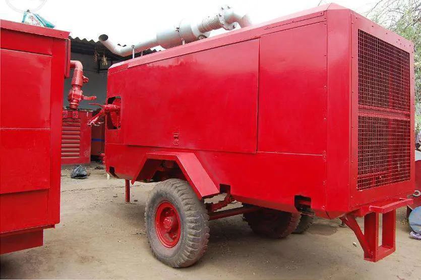
Reddy Compressors
The best position for a temporary compressed-air station is the position that supports reliable air delivery while controlling its effects on people, neighbouring premises and the working site. The shortest hose route is only one consideration. Cooling, exhaust, noise, structural support, access, drainage and the ability to maintain the equipment can determine whether a location remains workable throughout the hire period.
This guide helps plant engineers, facilities teams, rental coordinators and project managers compare locations for compressors, dryers, receivers, generators and associated temporary equipment. It develops the foundation, ventilation, intake-quality and access principles in the supplied Reddy Compressors material into a placement decision framework. It is planning guidance, not a universal installation drawing. All numerical examples are hypothetical. Equipment-specific clearances, competent site assessment and applicable local requirements govern the actual arrangement.
01 Define the complete station footprint
Draw the complete temporary-air station before choosing its location. Include compressors, treatment, receivers, electrical distribution, generators where used, fuel storage, condensate arrangements and connections to the permanent system. Allow space for operation, maintenance, deliveries and removal, rather than showing only the equipment skid dimensions.
Identify the services that must reach the station and the people who need access. A position may accommodate the compressor but leave no route for replacing a dryer, removing a cooler or safely connecting a fuel delivery. Such a location is not fully usable even if the equipment can initially be placed there.
State the intended duration and operating hours. A two-hour daytime task and a six-week continuous production duty create different exposure, servicing and community considerations. Include likely extensions in the review: temporary installations often remain longer than originally scheduled, and assumptions made for a short intervention may become unsuitable.
Separate installation space from operating clearance and controlled access. A painted outline around a machine does not establish a safe working area. Use the actual package instructions and site layout to define what must remain unobstructed during operation, maintenance and emergency response.
02 Map people and sensitive locations
Identify nearby workers, occupied buildings, security cabins, offices, residences, schools, healthcare premises and other sensitive users where relevant. Include doors, windows, ventilation intakes, public routes and places where people gather during breaks. The nearest property boundary may not be the nearest occupied or sensitive location.
Consider operating hours and occupancy. A location beside an empty workshop during the day may face occupied accommodation at night. A school or clinic may have specific periods when deliveries, noise or access restrictions are particularly disruptive. Record the relevant conditions instead of assuming one boundary reading represents every affected person.
Map indirect effects as well as compressor operation. Delivery vehicles, reversing alarms, refuelling, lighting, maintenance activity and repeated starts can affect neighbours. A station with acceptable steady sound may still generate complaints through avoidable late-night handling or glare directed at windows.
Keep the record proportionate and useful: receptor location, activity or occupancy, route of potential impact, operating period and proposed control. This gives the project team something concrete to review when the station changes, rather than a general statement that community considerations have been addressed.
03 Compare candidate positions using mandatory constraints
Shortlist locations against support, ventilation, exhaust separation, access, service routes, noise and environmental conditions. Identify conditions that make a position unacceptable unless resolved. A favourable cost or hose length cannot compensate for blocked emergency access or an unsupported slab.
Placement factor | Evidence needed | Decision affected |
|---|---|---|
Ground and structure | Equipment loads and verified support | Whether the location can carry the station |
Cooling and intake | Clearances, air paths and nearby contaminants | Thermal reliability and inlet conditions |
Exhaust | Discharge location and exposed people or intakes | Suitability for combustion equipment |
Noise | Source data, receptors and operating periods | Distance, orientation and mitigation |
Service routes | Hose, cable, fuel and drainage paths | Losses, access and installation scope |
Maintenance and removal | Service envelope and handling route | Usability throughout the hire |
Use scoring only after mandatory constraints have been checked. If scoring is used, show the assumptions and weights so the result is understandable. A location that wins because a serious unresolved issue received a low numerical weight has not been justified.
Record the selected position and the alternatives rejected. If conditions later change, that record helps the team reconsider an earlier option without restarting the entire survey or treating the original choice as permanently valid.
04 Verify support and stability
Confirm operating weight, point loads, support locations and the condition of the ground or structure. Account for fuel, fluids, ancillary equipment and any other loads on the same platform. A machine's transport weight may differ from its operating weight, and an average pressure over its overall footprint can conceal concentrated loads at feet or wheels.
For illustration, a 6,000 kg package has a static weight of approximately 58.9 kN using gravitational acceleration of 9.81 m/s². If the combined effective support area is assumed to be 0.40 m², average bearing pressure across those supports is about 147 kPa. This calculation is a screening input, not proof of ground or slab adequacy.
Actual design must consider load distribution, local slab bending or punching, settlement, dynamic effects and the condition below the surface. Underground services, trenches, covers and recent backfill may invalidate an apparently firm location. Obtain the appropriate structural or ground assessment where these conditions are uncertain.
Maintain the equipment's permitted level and support arrangement. Use manufacturer-approved provisions for stability, restraint and vibration control. Do not improvise levelling with unstable packing or assume a wheeled machine is secure because it has been detached from the towing vehicle.
05 Keep cooling air paths effective
Identify the separate inlet and discharge paths for each package. Cooling air leaving a compressor or generator can be substantially warmer than ambient air. If it returns to the inlet of the same machine or another unit, the station may operate in a locally hot environment even when the general site temperature appears acceptable.
Assess walls, roofs, containers, temporary screens and adjacent equipment that can redirect air. Wind direction matters, but reliance on a single prevailing wind is insufficient where reversing or calm conditions occur. Observe intake conditions during representative loaded operation, including the hottest relevant period where practicable.
Use the manufacturer's required clearances and allowable external resistance. A noise screen placed close to a cooling outlet may reduce direct sound while increasing recirculation or restricting flow. A temporary roof that protects against rain may trap hot air unless its geometry and openings are suitable.
Do not remove normal enclosure panels or defeat thermal protection to compensate for a poor location. If operation depends on leaving a protective enclosure open against the instructions, reassess the placement or cooling arrangement. Cooling reliability should be achieved by design, not by creating another hazard.
06 Use heat calculations as a screening tool
For a simplified enclosure heat balance, ventilation volume flow can be estimated as Q = H ÷ (ρ × cp × ΔT), where H is heat released to the enclosure in kW, ρ is air density in kg/m³, cp is specific heat in kJ/(kg·K), and ΔT is the permitted air-temperature rise in kelvin. The result is m³/s under the stated conditions.
Assume 100 kW of heat is released to the enclosure air, density is 1.2 kg/m³, specific heat is 1.005 kJ/(kg·K), and permitted rise is 10 K. The screening airflow is about 8.29 m³/s, or 29,850 m³/h. This is not a fan selection or an exhaust-dilution calculation.
The heat input must represent what actually enters that space. Do not equate engine shaft rating, fuel input and room heat without a suitable heat-rejection breakdown. Heat carried out through a dedicated duct or cooling-water circuit belongs in a different part of the balance.
A complete assessment also addresses combustion air where applicable, equipment cooling requirements, pressure losses, fan performance, short-circuiting of air paths and operating limits. A fan with an impressive free-air rating may deliver much less through the installed louvers and ductwork. Validate the arrangement using equipment data and commissioning observations.
07 Keep engine exhaust away from occupied air paths
Diesel engine exhaust requires deliberate placement control. Locate combustion equipment so that emissions do not enter occupied spaces, building air intakes or compressor suction through the expected operating conditions. Outdoor placement alone does not prove this: a courtyard, loading recess or narrow gap between buildings can restrict dispersion.
Distinguish engine exhaust from warm cooling air. Both need suitable discharge paths, but their hazards and engineering requirements differ. An arrangement adequate for removing heat is not automatically adequate for controlling exposure to engine emissions.
Do not treat open doors or a partly open canopy as proof that an enclosed location is suitable. Specialist assessment is needed where enclosure, nearby intakes or site geometry create uncertainty. Electric equipment may reduce local engine-exhaust issues, but a supporting generator can reintroduce them elsewhere on the site.
Any exhaust extension must be approved for the engine and installation, considering backpressure, temperature, support, fire exposure and discharge location. Improvised ducting can create mechanical and operating problems. An emissions label or absence of visible smoke does not establish that nearby people or air intakes are unaffected.
08 Protect compressor suction quality
Map dust-generating work, vehicle routes, welding, solvent use, chemical storage, steam vents and other potential contaminants near the intake. The supplied installation material correctly places clean intake air alongside cooling and filtration. A treatment train should not be used as an excuse to position its compressor in an avoidably contaminated environment.
Consider changes through the day. A clean area during the survey may become a truck queue, blasting zone or waste-handling area during operation. Coordinate with adjacent contractors so their activities do not create a new exposure after commissioning.
Identify sensitive end uses and their defined air-quality requirements. Oil-free compression does not mean that every contaminant in the surrounding atmosphere is removed, nor does it make the air suitable for breathing. Intake placement and downstream treatment must fit the specified application and measurement boundary.
Where intake relocation is proposed, check the manufacturer's requirements for duct resistance, filtration, weather protection and connection. Do not attach an arbitrarily long suction hose to solve a local contamination problem. A different equipment position may provide a more robust solution than adding another unverified restriction.
09 Specify noise information that can be compared
Request noise data for the actual equipment and operating state, with its measurement basis. Sound power and sound pressure are different quantities. A pressure level at a stated distance cannot be compared directly with a sound-power figure, and an unloaded rating may not represent operation at the required duty.
Identify whether the value is A-weighted, the stated distance and orientation, the operating condition and any relevant uncertainty. Seek information on tonal or low-frequency characteristics where these may influence the assessment. A single headline number is not a complete prediction of conditions at a neighbour's window.
Separate worker exposure from community assessment. Workers may spend time close to the package, while a nearby residence experiences the station over a longer period in a different acoustic setting. Applicable limits, measurement periods and assessment methods must be determined for the site; this article does not prescribe a universal acceptable boundary level.
Include other operating sources. Dryer regeneration, air discharge, generators, cooling fans and vehicles may contribute alongside the compressor. Opening enclosure doors for maintenance or operating under an abnormal condition can change the noise substantially and should be considered in the management plan.
10 Understand distance and multiple sources
For an ideal point source in a free field, with unchanged output and comparable geometry, the pressure-level change with distance is approximately L2 = L1 − 20 log10(r2/r1). This screening relationship predicts about 6 dB reduction for each doubling of distance. It is not reliable in every near-field, reflective or extended-source situation.
For illustration, an assumed 80 dB(A) at 5 m would screen as approximately 68 dB(A) at 20 m under those ideal conditions. Actual buildings, ground, barriers, wind and source directivity can change the result. The calculation does not demonstrate compliance or replace a suitable prediction and measurement plan.
Independent sound sources combine logarithmically. Two equal sources each contributing 68 dB(A) at the same receptor combine to about 71 dB(A), not 136 dB(A). Four such equal sources combine to about 74 dB(A). Assess the station operating configuration, not just the quietest individual machine.
Background sound must also be considered. If a hypothetical source contribution is 60 dB(A) and background is 57 dB(A) over a comparable assessment period, the energetic total is approximately 61.8 dB(A). A small total-level increase does not by itself resolve audibility, tonal character or acceptability. Interpret measurements using the appropriate method and site context.
11 Choose noise measures without impairing operation
Consider quieter equipment, suitable distance, orientation and operating schedules before relying on add-on barriers. Keep normal acoustic enclosures maintained and operated as intended. Loose panels, damaged seals or an abnormal discharge can undermine an otherwise reasonable placement decision.
Barriers can interrupt a direct sound path, but their effect depends on geometry, gaps, frequency and reflected paths. They may be less effective for low-frequency sound. A generic screen should not be assigned a guaranteed reduction without design evidence for the actual source and receptor arrangement.
Coordinate barrier design with cooling, exhaust, fire considerations, wind loading, access and visibility. A screen that conceals a delivery vehicle from pedestrians or redirects exhaust toward a building creates a new problem. The layout must remain workable with the mitigation installed, not only before it is added.
Worker hearing protection is a personal exposure measure; it does not reduce sound reaching neighbouring premises. Community impact requires source, path or operating controls appropriate to the affected locations. If specialist acoustic work is necessary, define the operating scenarios and receptors clearly so the assessment answers the project question.
12 Check vibration paths and structural connections
Consider how vibration can travel through supports, floors, rigid pipes and nearby structures. Ground-level placement beside a lightweight building may have different consequences from placement on an isolated hardstanding. Sensitive equipment, laboratories or occupied rooms can require a more detailed assessment than a general visual inspection.
Use the manufacturer's mounting arrangement and any specified vibration isolation. Flexible air connections may reduce transmission through pipework, but they do not correct an inadequate foundation or automatically isolate every vibration path. Their pressure rating, restraint and movement requirements still apply.
Investigate reported vibration using operating conditions and suitable measurements. Record whether it appears during starting, loaded operation, unloading or a particular machine combination. Avoid declaring structural damage, safety or acceptability from subjective impressions alone.
Where a proposed location is above occupied space or on a structure with uncertain capacity, obtain appropriate engineering review before placement. Temporary status does not remove the need to establish structural suitability and the effect of the installed equipment.
13 Protect movement and emergency access
Plan pedestrian and vehicle routes around the station, including deliveries and servicing. Keep required escape routes, fire access, isolation points and emergency equipment available. The station should not force people into a vehicle lane or require them to step across pressurised hoses to reach a control point.
Identify traffic interactions at gates, corners and loading areas. A fuel tanker or service vehicle may occupy more space than the compressor itself and may need a different approach route. Schedule or redesign these movements before they become routine conflicts.
Hose and cable crossings need suitable planned protection, access control and inspection. Do not treat a loose covering or an improvised ramp as an adequate solution for every vehicle and pedestrian condition. Check loads, route visibility and the consequences if a crossing becomes damaged.
Provide clear identification and appropriate separation from unauthorised access. Secure access should still allow authorised response without delay. A locked enclosure is not helpful if nobody on the operating shift can reach the emergency controls or identify which source feeds the temporary air station.
14 Account for weather and water movement
Review drainage, flood exposure, runoff routes, wind and the equipment's permitted environmental conditions. A low point that appears convenient in dry weather may collect water during rain. Check how water flows from roofs, paved areas and nearby operations rather than considering only rain falling directly onto the package.
Keep electrical equipment, fuel arrangements and treatment drains suitable for the location. Protect intake openings without restricting required airflow. Weather covers and temporary roofs must have suitable support and clearance; adding a tarpaulin over operating machinery can interfere with heat rejection or introduce other hazards.
Control condensate through the specified collection and treatment arrangements. Do not assume compressor condensate can be discharged to a surface drain because the equipment is temporary or oil-free. Its composition and the applicable discharge requirements determine the correct route.
Inspect after weather events that could alter support, drainage or barriers. Settlement, washout, debris and displaced screens can change the operating conditions even when the compressor itself remains undamaged. Relocation may be necessary if the original assumptions no longer hold.
15 Balance distance with pressure and electrical losses
Moving the station away from occupied areas can improve placement but lengthen air and electrical routes. Calculate those consequences rather than rejecting a quieter location automatically or compensating by raising pressure without assessment. Larger distribution components or a revised route may resolve the trade-off.
For illustration, an end use requires 6.0 barg. Assumed treatment loss is 0.30 bar, manifold loss is 0.15 bar and temporary hose loss from position A is 0.25 bar. Required upstream pressure is therefore 6.70 barg before justified control allowances. At position B, assumed hose loss is 0.65 bar, increasing that requirement to 7.10 barg.
If the available package cannot support the revised duty, position B is not automatically unusable: a larger hose or another route may reduce loss. The corrected pressure and flow assessment must use the actual arrangement. Do not assume the compressor's rated airflow remains unchanged at a different operating pressure.
Placement is therefore a system decision whose effects must be carried into the connected engineering records.
16 Work through a realistic location comparison
Assume a temporary station has two possible locations. Position A is 35 m from the air tie-in and close to an occupied office. Position B is 80 m from the tie-in, farther from occupied rooms, but has an unresolved ground-support condition. The compressor's exact acoustic and cooling information is still needed for both.
Issue | Position A | Position B |
|---|---|---|
Air route | Shorter route with lower assumed loss | Longer route requiring sizing review |
Occupied areas | Office nearby | Greater separation from occupied rooms |
Exhaust and cooling | Building openings require assessment | Air paths still require verification |
Support | Existing hardstanding to be confirmed | Ground capacity unresolved |
Delivery access | Shared with office access | Separate approach may be possible |
Decision status | Conditional on impact controls | Conditional on support and route design |
Neither option is approved by this comparison. Position B's apparent community advantage does not resolve its ground condition, while position A's convenience does not resolve its effects on occupied rooms. Obtain the missing evidence, then compare the complete installed and operating arrangements.
Document the final choice in a placement drawing showing equipment orientation, service envelopes, receptors, routes and controls. Include the conditions that would require reconsideration, such as adding a second unit, changing operating hours or moving a nearby building intake.
17 Communicate the operating plan clearly
Where neighbouring occupiers may be affected, the site should identify an appropriate contact and explain the relevant operating period, expected activities and how concerns can be reported. Keep communication factual and proportionate. Do not promise silent operation or give unverified levels as guarantees.
Coordinate deliveries, startup tests and maintenance with the site's communication arrangements. A planned noisy event is easier to manage when its timing and responsible person are clear. Notification does not replace technical controls or any required approvals, but it can prevent avoidable confusion.
Provide operators with a simple escalation route for complaints about sound, fumes, vibration, lighting or access. Record the time, location, equipment state and reported effect. A complaint may reveal a wind-dependent exhaust path or night-time operating condition that was absent during the daytime survey.
Avoid dismissing concerns solely because a previous measurement was acceptable. Check whether the condition, receptor or operating configuration has changed. Equally, do not attribute every nearby disturbance to the temporary compressor without evidence. Investigate the actual event and retain the findings.
18 Verify placement during commissioning
Inspect the as-installed layout against the placement plan before service. Confirm orientation, support, clearances, controls, access, routes, drainage and installed mitigation. Equipment substitutions and practical changes made during unloading must be reconciled with the design rather than accepted as harmless by default.
Observe representative loaded operation. Check intake temperature, cooling discharge paths, alarms, visible recirculation concerns, exhaust direction and delivery pressure at the required boundary. Use suitable measurements and competent assessment for noise or exposure where needed; absence of a complaint during a short trial is not proof of acceptability.
For acoustic records, note machine combination, loading, enclosure condition, measurement position, weather and other significant sources. Record the method and instrument suitability. Without that context, a single decibel value is difficult to compare with a later reading or a project criterion.
Close material findings before relying on the station for the intended service. If full operating conditions cannot be tested immediately, state the verified operating envelope and the remaining observation required. Do not convert an untested assumption into an unconditional acceptance statement.
19 Maintain and revise the placement record
Temporary sites change. New containers, scaffolding, parked vehicles, material stacks or acoustic screens can obstruct air paths and access. Revisit the layout when these changes occur, when hours extend into the night or when another compressor is added.
Adding an identical unit can change combined sound, heat rejection, fuel demand and access requirements. It may also increase hose congestion and shared failure exposure. Review the combined station rather than approving the additional machine solely because the first one worked satisfactorily.
Inspect the condition of barriers, mounts, drains and protected crossings during the hire. Record abnormal temperatures, recurring complaints and access conflicts so patterns can be addressed. Remove redundant temporary items that obstruct the approved operating area through the site's controlled process.
For a Reddy Compressors enquiry, share site photographs or drawings, air duty, operating hours, candidate positions, nearby occupancy and available services. Secunderabad and Hyderabad form the operating base, with Telangana and Andhra Pradesh as priority regions. Wider support and specialist surveys depend on confirmed scope and resources. Final placement should be agreed for the selected package and actual site conditions.
20 Frequently asked questions
How far should a rental compressor be from a building
There is no universal distance covering every package and site. Use manufacturer clearances and assess cooling, exhaust, noise, access, openings and the building's occupancy. A distance that meets one requirement may still be unsuitable for another.
Can temporary acoustic screens be placed around the compressor
Only after their acoustic and operational effects are assessed. Screens must not obstruct cooling, redirect exhaust into occupied areas, restrict access or create unstable structures. Their noise benefit depends on the actual geometry and sound characteristics.
Does outdoor placement make diesel exhaust harmless
No. Exhaust can reach doors, air intakes, work areas and partly enclosed spaces. Review the discharge path and site geometry under relevant conditions, and obtain specialist assessment where exposure is uncertain.
Will moving the compressor twice as far away halve the noise
Noise should be assessed in decibels with a suitable model. An ideal point source in a free field reduces by about 6 dB when distance doubles, but reflections, source size and other conditions can change the result. This is not a universal rule for perceived loudness or compliance.
Can a normal factory floor support a temporary compressor
It must be checked for the actual loads and support arrangement. Overall machine weight and footprint do not establish local slab or ground capacity. Underground services, covers, deterioration and concentrated loads may require additional assessment.
Should the quietest location always be selected
Select the location that meets all mandatory requirements and provides the best overall operating arrangement. A quieter position may need a larger air main, revised electrical supply or improved support. Resolve those effects rather than choosing on one factor alone.
Sources and evidence basis
22 Sources and technical basis
Owner-supplied source: B.A. (19-7-26) RC Tips, supplied PDF. Foundation, ventilation and intake-quality sections establish the need for stable support, maintenance access, heat removal and separation from contaminants. These principles informed the placement framework; the source is not a structural assessment or package-specific clearance schedule.
Atlas Copco, Compressor Placement and Optimal Working Conditions. Manufacturer reference identifying ventilation, noise, drainage, hazardous surroundings and service access as installation considerations. https://www.atlascopco.com/en-ie/compressors/compressed-air-tips/optimal-working-conditions-compressor-room
UK Health and Safety Executive, Workplace design. Reference for reducing noise through layout, separation and appropriate barriers, including limitations from reflections and low-frequency sound. https://www.hse.gov.uk/noise/goodpractice/workplacedesign.htm
UK Health and Safety Executive, Cancer and construction Diesel engine exhaust emissions, and Control of diesel engine exhaust emissions in the workplace HSG187. References supporting deliberate control of exposure to diesel emissions. These are UK guidance, not certification of compliance for an Indian installation. https://www.hse.gov.uk/construction/healthrisks/cancer-and-construction/diesel-engine-exhaust.htm and https://www.hse.gov.uk/pubns/books/hsg187.htm
Public references checked for this edition on 3 October 2026. Heat, support, pressure and acoustic examples are original illustrative calculations using stated assumptions. They do not replace equipment documentation, structural review, acoustic or exposure assessment, or applicable local requirements. No particular location, noise limit, clearance or installation has been certified by this article.