
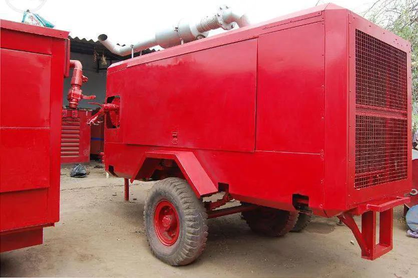
Reddy Compressors
A temporary compressed-air system is accepted when evidence shows that it delivers the agreed pressure, net flow, air quality and operating response at the specified receiving boundary. Starting the compressor and observing pressure on its controller demonstrates only part of that result. The installed treatment, distribution, utilities and controls must perform together under the duty that matters to the receiving process.
This guide helps plant engineers, maintenance teams, rental coordinators, quality personnel and operating managers plan commissioning and record a defensible acceptance decision. It develops the commissioning and treatment principles in the supplied Reddy Compressors material into a practical framework for temporary installations. It is not a universal valve sequence, electrical test procedure or pressure-test instruction. Competent authorised personnel must use equipment instructions and the approved site method. All numerical examples are hypothetical and do not certify a particular installation.
01 Agree what acceptance must demonstrate
Define the service before writing the test. Specify net delivered flow, minimum and maximum pressure, air-quality requirements, operating hours, significant demand events and permitted interruption. State the exact receiving boundary: compressor outlet, treatment outlet, plant header or critical point of use. These locations are not interchangeable.
Clarify whether the temporary system replaces the complete station, supplements permanent compressors or supplies a restricted set of users. The acceptance plan should reflect that arrangement. A test with permanent machines supporting the header cannot demonstrate the temporary package's standalone capability unless their contribution is measured and accounted for.
Identify the intended operating envelope, including ambient conditions, duty combinations and utility sources. Where the installation is expected to operate on both utility power and a generator, the relevant conditions may require separate verification.
Agree who witnesses results, interprets deviations and authorises release. Commercial receipt of the equipment, technical acceptance of the air service and statutory or site-required examination are separate matters. Record each according to its purpose rather than allowing one signature to imply all three.
02 Turn requirements into observable criteria
Every important requirement needs a measurement or other suitable evidence, an acceptance condition and a defined observation period. Replace statements such as pressure satisfactory with the specified pressure range, location, demand condition and permitted transient behaviour. Avoid universal limits that are unrelated to the process or equipment.
For illustration, a project might require at least 6.2 barg at a critical user while receiving 18 reference m³/min, with a separately defined short-duration demand event and an upper pressure limit established from the installed system. These are hypothetical requirements, not recommended settings. The test must demonstrate the stated combination rather than flow at one pressure and pressure at another operating point.
Distinguish continuous-duty criteria from event criteria. An average pressure can be acceptable while a short dip interrupts an actuator. Conversely, a brief event should be evaluated against its agreed duration and consequence rather than automatically treated as failure of steady-state capacity.
Define the decision rule for measurements close to a limit, including how uncertainty will be considered. Agree this before testing. Selecting a favourable interpretation only after seeing a marginal result undermines the acceptance record.
03 Confirm installation readiness before operation
Review the installed equipment against the selected duty and mobilisation record. Confirm identities, pressure and temperature ratings, treatment sequence, supports, interfaces, hose condition, restraints where required, drainage and access. Resolve transit damage and missing components before relying on the system for service.
Check electrical or fuel arrangements through the responsible specialists. Confirm that the package can operate on the intended source and that its auxiliaries are included. A compressor may run while an external dryer or drain has no usable supply, leaving the air-service requirement unmet.
Verify the placement assumptions: cooling paths, intake condition, exhaust arrangements where applicable and maintenance space. Commissioning should not proceed on the assumption that overheating or poor ventilation can be corrected later while the station is carrying production.
Apply these checks through the selected equipment's procedures. In particular, rotation verification and electrical work must not be improvised by unqualified personnel or performed using a generic method from a website article.
04 Establish the pressure system boundary
Identify all components exposed to pressure and their applicable operating limits. Include temporary hoses, fittings, filters, receivers and any sections of permanent plant brought into the arrangement. The safe operating envelope is not established by the compressor's maximum rating alone.
Confirm the protective arrangement remains effective in every intended operating and isolation state. A receiver or trapped section must not lose required protection because a valve is closed during a transfer. Check this against the actual drawing and field installation, including connections to other sources.
Distinguish operational commissioning from proof testing or formal examination. A pressure gauge holding steady does not replace an examination required for the installed system. Any pressure or integrity test must follow an appropriate approved method with competent personnel; compressed air can store significant energy, so casual overpressure testing is unacceptable.
Use the requirements applicable to the actual jurisdiction and equipment. HSE guidance is useful for the principle of knowing safe operating limits and examination responsibilities, but UK requirements must not be presented as proof of compliance for an Indian installation.
05 Create a test plan with named responsibilities
The test plan should identify the installed configuration, operating conditions, instruments, sampling locations, observation periods, witnesses, stop conditions and evidence to retain. Allocate responsibility for package operation, plant demand, electrical observations, air-quality sampling and the final decision.
Test subject | Evidence to obtain | Decision supported |
|---|---|---|
Installation readiness | Completed checks and resolved defects | Ready for controlled operation |
Pressure and flow | Simultaneous readings at defined boundaries | Required service can be delivered |
Air quality | Results for the specified contaminants and basis | Intended users can receive the air |
Controls and events | Logged response to agreed operating scenarios | System remains within accepted behaviour |
Utilities and thermal duty | Relevant supply and temperature records | Duty can be sustained |
Handover | Operating limits, contacts and instructions | Team can operate the accepted arrangement |
Plan coordination with production. Tests involving demand changes, source transfer or interrupted supply need the plant authority's agreement and a suitable fallback. Do not introduce an unplanned process upset solely to collect a commissioning result.
Identify which results are available immediately and which depend on laboratory analysis or later operating conditions. This allows an honest release decision instead of assuming that all acceptance evidence will exist on the day equipment arrives.
06 Use suitable instruments and locations
Select instruments with appropriate range, accuracy, response and condition for the measurement. Record identification, calibration or verification status, installation location and the units used. A valid calibration certificate does not correct an unsuitable sampling point or an installation outside the instrument's permitted conditions.
For flow measurement, confirm the meter's reference basis, required straight lengths, pressure and temperature compensation, turndown and suitability for the air condition. Moisture, pulsation or disturbed flow can affect particular technologies. Follow the meter instructions rather than fitting it wherever a spare connection happens to be available.
Pressure should be measured where the requirement applies, with additional points chosen to locate losses. A controller display inside the package may be useful operationally but is not automatically the acceptance instrument for a distant user. Check the relationship between each indication and the actual pressure boundary.
Synchronise time across loggers and operating records. Choose logging intervals and sensor response fast enough for the events being assessed. A one-minute record may show a normal average while missing a damaging two-second pressure dip. Preserve raw data where practical so later review does not depend only on a plotted summary.
07 Keep flow reference conditions explicit
Compressed-air flow can be reported as actual volume at line conditions, free air delivery or volume normalised to specified reference conditions. State which quantity is being used and the pressure, temperature and humidity basis where relevant. Do not compare numbers carrying the same m³/min label if their bases differ.
For an ideal dry-gas illustration, reference volume flow is Qref = Qline × (Pline,abs ÷ Pref,abs) × (Tref ÷ Tline). Temperatures are in kelvin and pressures are absolute. More complete conversions may require compressibility and moisture treatment. Gauge pressure must not be inserted directly into the pressure ratio.
Suppose actual line flow is 2.0 m³/min at 8 bara and 30°C. With a hypothetical reference of 1 bara and 20°C, the ideal conversion is 2.0 × 8 × 293.15 ÷ 303.15, approximately 15.47 reference m³/min. This is not 16 reference m³/min once temperature is included, and it is not automatically a compressor FAD test result.
Keep the declared reference consistent across compressor capacity, process demand, purge losses and acceptance flow. Where a supplier's performance declaration follows a particular test basis, obtain the relevant documentation instead of relabelling an informal site measurement as a standardised performance test.
08 Demonstrate net delivery after treatment
The receiving process needs useful air after treatment losses, purge and other demands that fall within the supply boundary. Record where flow is measured and whether the result includes air that never reaches the intended users. A gross compressor figure alone cannot demonstrate the net duty.
For illustration, a package produces 22 reference m³/min. If assumed dryer purge is 12% of that gross flow, purge is 2.64 reference m³/min. If another 0.30 reference m³/min is consumed by auxiliaries inside the boundary, estimated net delivery is 19.06 reference m³/min. Against a requirement of 18, the arithmetic margin is 1.06 reference m³/min before uncertainty and other conditions.
This calculation assumes purge is proportional to gross flow. Some treatment arrangements use a different control or consumption basis. Obtain the actual data, and avoid applying a percentage model merely because it is convenient.
Where direct measurement of net flow is practical and suitable, it can reduce reliance on assumed component losses. In either case, verify the flow at the required pressure and treatment condition. Capacity available during a bypassed or unstabilised treatment state is not evidence of the specified useful-air service.
09 Measure pressure at the critical users
Log pressure through representative steady demand and agreed peak events. Identify minimum, maximum and recovery behaviour at the receiving boundary. Record the operating machines and relevant control states so the result can be interpreted rather than treated as an unexplained pressure trace.
A hypothetical station measures 7.2 barg at compressor discharge, 6.8 barg after treatment, 6.4 barg at the temporary manifold and 6.1 barg at a critical user during the same stable flow condition. The observed drops are 0.4, 0.4 and 0.3 bar across those sections. If the user requires 6.2 barg, the measured result is short by 0.1 bar before applying the agreed uncertainty rule.
Do not automatically raise the compressor setpoint. Investigate restrictions, component selection, hose routing, filter condition, valve positions and measurement validity. Any revised pressure must remain compatible with all equipment limits, controls and the package's delivered capacity.
Pressure readings taken at different times and demand states should not be subtracted as if they describe the same flow path condition. Simultaneous or otherwise properly controlled measurements make the diagnosis meaningful and reduce unnecessary changes to equipment that may be functioning correctly.
10 Verify the specified air quality at the receiving boundary
Define the contaminants relevant to the application and the required limits or purity classes. Where ISO 8573 terminology is used, state the required particle, water and oil specifications explicitly, together with any additional process requirements. A statement such as clean dry air is not a complete acceptance criterion.
Select sampling methods and locations appropriate to each property. Pressure dew point, liquid water, particles and oil are not established by the same instrument or observation. Oil-free compressor technology does not by itself demonstrate the entire installed system's air quality, particularly after hoses and permanent pipework with an uncertain history.
Record the sample pressure, operating condition, sampling arrangement and stabilisation. Use suitably competent testing personnel and laboratory support where required. The CAGI purity guidance helps frame the specification, but the actual method and limits must match the project's required evidence.
Do not extend ordinary industrial-air acceptance to breathing, medical or other specialist applications. Those uses require their own specifications and verification. Likewise, a satisfactory dew-point reading should not be described as a pass for all contaminants when only moisture has been measured.
11 Allow treatment to reach the relevant operating state
Follow the dryer and filter suppliers' startup and operating instructions. Some systems need stabilisation before the intended quality can be demonstrated. Recently connected downstream piping may also contribute moisture or contaminants that are not represented by a measurement immediately after the dryer.
Observe the relevant operating cycle. An adsorption dryer may have regeneration and switching events, while a refrigerated dryer responds to changes in inlet temperature and load. A short favourable reading can miss the condition that governs acceptance. Select observation duration from the equipment behaviour and process need rather than a universal number of minutes.
For illustration, a project requires pressure dew point at or below −40°C at a defined pressure and location. A reading of −42°C under the specified steady condition is relevant evidence, but it does not establish performance during a later switching event if that event was excluded. The −40°C value is a hypothetical project requirement, not a universal instrument-air rule.
If a result later rises to −32°C under an intended operating condition, the system does not meet that stated moisture requirement for that condition. Investigate capacity, inlet conditions, purge, regeneration, controls and sampling before deciding on corrective work. Do not average away a quality excursion that the process specification does not permit.
12 Assess demand events and storage support
Define relevant transient demand: simultaneous tool use, actuator events, production restart or another repeatable process condition. Record event magnitude, duration, frequency and required recovery. A storage calculation can support the plan, but acceptance should address the installed response.
Suppose normal demand is 18 reference m³/min and a 30-second event requires 24 reference m³/min. If net incoming supply remains 20 reference m³/min, the event deficit is 4 × 0.5 = 2 reference m³. An idealised receiver using a 1 bar absolute-pressure reduction at a 1 bara reference and equal-temperature assumptions would require 2 m³ of receiver volume for that deficit.
This screening calculation omits dynamic thermal effects, distribution losses and other practical constraints. It does not establish the usable reserve at the critical user. The permitted pressure band must be derived from the actual process requirement, not selected simply to make the storage result smaller.
After the event, the 2 reference m³ deficit would take about one minute to replenish at a 2 reference m³/min surplus under the same ideal assumptions. If events repeat sooner, storage may not recover. Test the relevant sequence rather than demonstrating only one isolated event from a fully charged receiver.
13 Verify control interaction and protection
Confirm setpoints, sequencing, permitted operating modes and interactions between temporary and permanent sources. Identify which controller governs header pressure and how units load, unload, stop or restart. A stable compressor on its own can behave differently when connected to another pressure-controlled source.
Use the approved methods to verify alarms, interlocks and protective functions. Some checks may use documented simulation or manufacturer procedures rather than creating the hazardous condition itself. Do not defeat protection, deliberately overpressurise the system or provoke an unsafe fault to obtain a test result.
Record the expected and observed response for each relevant function. Include treatment alarms and loss of auxiliaries, not just compressor faults. If a dryer fails while the compressor continues delivering air, the process response must match the application's quality requirements and the authorised operating plan.
Restore and document the final operating configuration after any approved test mode. Temporary overrides or test settings must not remain hidden in the handover. The operator should receive the accepted configuration, its limits and the instructions for responding to abnormal conditions.
14 Demonstrate utilities and thermal duty together
Observe electrical or fuel performance under representative air load. For electric packages, include relevant starting, voltage, current and power observations through the responsible electrical team. For diesel arrangements, verify operating fuel readiness and monitor relevant engine indications using the equipment instructions.
Include external auxiliaries such as dryers, pumps and cooling fans. A compressor running normally does not establish that the complete treatment train remains energised or that required cooling is available. Record utilities at the same time as air performance where their interaction matters.
Check temperatures and cooling behaviour over a period sufficient to represent the duty being accepted. A cold-start trial may not expose heat recirculation or a sustained thermal limitation. Where the hottest expected ambient condition cannot be reproduced, combine equipment evidence and site assessment with a clearly stated limitation on what the test proved.
Avoid claiming all-weather or continuous-duty acceptance from a brief lightly loaded run. Establish the operating conditions actually demonstrated and any monitoring or further verification needed when the station reaches a different condition.
15 Plan changeover and recovery tests around the process
Where continuity is required, verify the agreed transfer or recovery scenario with plant authorisation and a suitable fallback. Define which pressure, quality and interruption limits apply, who controls the test and who can stop it. The test should answer a specific operating question rather than create an uncontrolled outage.
For illustration, assume useful-air recovery after a source loss is measured as 45 seconds. An idealised 3 m³ receiver falling from 8 bara to 7 bara at a 1 bara reference provides about 3 reference m³. At an essential demand of 6 reference m³/min with no incoming air, theoretical support is 30 seconds. The example therefore has a 15-second mismatch before practical losses are considered.
That mismatch cannot be accepted as uninterrupted service. Revise the supply strategy, reserve or process response and verify the revised arrangement. A fast electrical transfer does not establish useful-air recovery if compressor acceleration or treatment readiness takes longer.
Where a live failure test would create unacceptable process risk, use an agreed alternative verification strategy and state its limitations. Documented design evidence, controlled simulations and staged testing can support a decision, but must not be described as a full live demonstration if they were not one.
16 Interpret measurement uncertainty honestly
State the material sources and apply the decision rule agreed before the test. Extra decimal places do not make a borderline result more reliable.
Suppose required minimum flow is 18.0 reference m³/min, measured flow is 18.3 and the reported uncertainty is ±0.6 reference m³/min on its stated basis. The lower end is 17.7. Under a pre-agreed conservative rule requiring the lower bound to meet the minimum, this result would not demonstrate a pass. Another contract may use a different decision rule, but it must be explicit.
Do not simply subtract every tolerance from every result without considering the measurement model. Equally, do not ignore uncertainty because the central value is favourable. Obtain appropriate measurement expertise where the decision has significant technical or commercial consequences.
Repeated measurements can help distinguish changing process conditions from random variation, but they do not automatically remove systematic error. Check the setup and basis first. A consistently misconfigured flow meter can produce a highly repeatable incorrect answer.
17 Correct defects and retest the affected functions
Record each finding with its evidence, affected requirement, responsible party and disposition. Separate defects preventing safe or suitable operation from minor matters that do not affect the agreed service. The decision should follow the actual consequence, not a desire to report that commissioning is complete.
After corrective work, retest the functions that may have changed. Replacing a restrictive hose requires pressure and delivery review; changing a dryer can affect quality, purge and utilities; altering a control setting can affect several operating states. Use a focused retest that addresses the modification and its relevant interactions.
Keep the original result and the corrected result. Replacing a failed value in the record without retaining the change obscures what was demonstrated and when. A concise record of finding, action and retest is more useful than an unexplained final pass mark.
Do not close a technical issue solely because equipment was serviced. A maintenance action may be necessary, but its effectiveness must be established against the failed requirement. Acceptance concerns the resulting performance and operating condition, not simply completion of a work order.
18 Make a precise release decision
The release record should state whether the system is accepted for the agreed duty, accepted within a clearly limited operating envelope, or not ready for service. Avoid ambiguous wording that allows an unresolved material requirement to disappear inside a general statement of conditional acceptance.
A restricted release may be appropriate only where the responsible authorities determine that the allowed duty is safe and suitable. Define the permitted users, flow, pressure, hours or other restrictions; the evidence supporting them; who controls them; and when further verification is required. Restrictions must be practicable to enforce.
For example, demonstrating 12 reference m³/min for a defined workshop load does not establish acceptance for an untested 18 reference m³/min production duty. A valid limited result should be retained as such, rather than inflated into a full-station claim.
Do not allow commercial urgency to substitute for missing safety or quality evidence. If an essential result is pending, record what remains unavailable and how the plant will maintain its required service until that evidence exists. The release decision belongs to the authorised project parties, not to an automatically generated checklist.
19 Hand over the accepted operating baseline
Provide the equipment register, final configuration, measured baseline, accepted duty, operating limits, alarm response, maintenance requirements and support contacts. Include instrument and sampling information needed to interpret the results later. The operating team should understand what was tested and what was not.
Handover record | Minimum useful content | Purpose during operation |
|---|---|---|
Accepted duty | Flow, pressure, quality and operating scenarios | Defines the service commitment |
Installed configuration | Equipment identities and final connection drawing | Prevents unintended changes |
Test evidence | Conditions, instruments, results and decision rule | Supports later comparison |
Defect disposition | Corrections, retests and remaining restrictions | Keeps limitations visible |
Operating instructions | Alarms, response and escalation contacts | Supports controlled operation |
Change triggers | Relocation, added loads, substitutions or settings | Identifies when revalidation is needed |
Use this baseline for subsequent shifts and periodic review. A fall in user pressure should be compared with the accepted flow and configuration, not only with a remembered controller reading. Recommission relevant functions after changes that invalidate the original assumptions.
For a Reddy Compressors enquiry, provide the required duty, receiving boundary, quality specification, critical events and acceptance documentation needed. Secunderabad and Hyderabad form the operating base, with Telangana and Andhra Pradesh as priority regions. Wider project support and specialist testing depend on confirmed scope and resources; no generic page should imply that every test or laboratory service is automatically included.
20 Frequently asked questions
Is a compressor running normally enough for acceptance
No. The installed system must demonstrate the agreed pressure, net flow, quality and operating response at the defined receiving boundary. Treatment, distribution, utilities and controls are part of that result.
Where should commissioning pressure be measured
At the location where the requirement applies, with additional points selected to locate losses. A package controller reading alone cannot demonstrate pressure at a distant critical user. Compare readings under the same demand conditions.
Does oil free equipment prove the required air quality
No. The complete installed system and relevant contaminants must be evaluated against the application specification. Hoses, pipework, intake conditions and treatment can affect the delivered result. Moisture, particles and oil require appropriate evidence.
How long should a commissioning trial run
Long enough to assess the relevant thermal behaviour, treatment cycles, demand events and operating scenarios. There is no universal duration suitable for every installation. State any conditions not demonstrated during the available trial.
Can average pressure hide an acceptance failure
Yes. A short pressure dip may affect a user even when the average is satisfactory. Use suitable instrument response and logging intervals, and compare the event with the specified pressure and interruption criteria.
Does commissioning replace a required pressure system examination
No. Operational demonstration, equipment inspection and any examination required under applicable rules have different purposes. Establish the obligations for the actual installation and retain the relevant records separately.
Sources and evidence basis
22 Sources and technical basis
Owner-supplied source: B.A. (19-7-26) RC Tips, supplied PDF, Commission Before Production section. It identifies foundation, electrical, cooling, pressure, protective devices, piping, treatment and drain checks. These principles informed the commissioning-readiness framework; the document does not provide a test procedure for every package.
Owner-supplied source: B.A. (21-7-26) RC 2, supplied PDF, treatment and point-of-use sections. It links delivered-air requirements to the needs of the receiving application. This article preserves that boundary-based approach without converting general application descriptions into universal purity limits.
Compressed Air and Gas Institute, Working With Compressed Air and the referenced Compressed Air Purity Guide. Industry references for defining compressed-air purity using appropriate contaminant specifications and treatment selection. https://www.cagi.org/working-with-compressed-air/
UK Health and Safety Executive, Introduction to pressure equipment, and Using pressure systems. References for establishing safe operating conditions and the role of examination. Their UK regulatory context does not certify compliance for an Indian installation. https://www.hse.gov.uk/pressure-systems/about.htm and https://www.hse.gov.uk/pressure-systems/user.htm
Atlas Copco Specialty Rental India. Manufacturer rental reference identifying commissioning and on-site support as parts of the complete rental-service lifecycle. It does not establish Reddy Compressors testing scope or guaranteed service availability. https://www.atlascopco.com/en-in/rental
References checked for this edition on 3 October 2026. All flow, pressure, moisture, storage and uncertainty examples are original illustrative assumptions. Actual acceptance requires selected-equipment documentation, verified site measurements, suitable testing methods, agreed decision criteria and applicable local requirements. No installation or purity class has been certified by this article.