
Interactive resource
Use the working tool for this page
This page has a matching worksheet, calculator or comparison resource. It runs in your browser: enter your own measured values and keep the evidence behind every result.
Open resourceRoute: /engineering-tools/abrasive-blasting-air-demand-calculator/ (proposed until route reconciliation).
1. Purpose and Engineering Decision
Abrasive blasting is a high, sustained compressed-air load. The compressor must supply enough air to maintain the required pressure while the nozzle is flowing, not merely reach the desired pressure with the blast valve closed. Nozzle diameter, nozzle wear, operating pressure, simultaneous nozzles, hose/manifold losses and auxiliary air users all affect the total compressor requirement.
Mode | Primary output |
|---|---|
Single nozzle | Verified nozzle air demand at selected pressure |
Multiple nozzles | Simultaneous blasting demand |
Wear scenario | Demand increase as effective nozzle bore enlarges |
System total | Nozzles + verified auxiliaries + explicit reserve |
Compressor comparison | PASS/HOLD/FAIL at required compressor pressure-flow point |
2. Required Asset - Nozzle Demand Tool with Source-Chart Version
Field 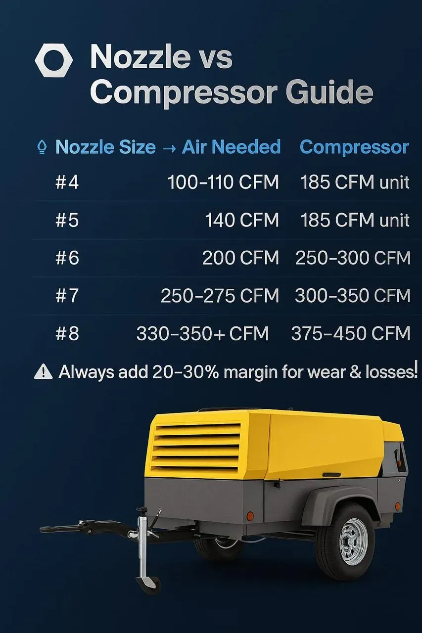 | Input / lookup | Control |
|---|---|---|
Nozzle type / series | User input | Record manufacturer or chart family |
Nominal nozzle bore | User input | mm or inch |
Effective/worn bore | Optional measured input | Use when known |
Required nozzle pressure | User input | Pressure at nozzle, not compressor |
Source chart title | Required | Exact document / table |
Source revision/date | Required | Version controlled |
Chart pressure basis | Required | psi/bar and gauge/absolute where stated |
Chart flow basis | Required | cfm/FAD/SCFM/etc. |
Per-nozzle demand | Lookup | No silent interpolation unless source permits |
Nozzle count | User input | Integer >=1 |
Simultaneity | User input | Explicit |
Auxiliary users | Entered separately | Breathing/control/other verified demand |
Total air demand | Calculated | Common flow basis |
3. Why the Source Chart Must Be Preserved
Published nozzle-demand tables may differ by nozzle geometry, test basis, pressure definition and rounding. A value copied into a quotation without its source version is treated as provisional.
Abrasive blasting as a legitimate portable-compressor application, but it does not provide one complete nozzle-consumption chart suitable for universal lookup.
4. Core Demand Calculation
Q_nozzles = Q_per_nozzle x Number_of_nozzles x Simultaneity_Factor
Q_total = Q_nozzles + Sum(Q_auxiliary) + Q_explicit_reserve
The simultaneity factor is normally 1.0 when all listed nozzles can blast at the same time. A lower value requires an operating rule or project basis; it must not be assumed simply to reduce compressor size.
5. Nozzle Pressure Is the Governing Pressure
The required blasting pressure belongs at the nozzle. The compressor discharge pressure must be higher by the pressure losses through aftercoolers, separators, manifolds, hoses, valves and couplings.
P_compressor_required = P_nozzle_required + DeltaP_delivery_path
6. Nozzle Wear
Abrasive wear can enlarge the effective nozzle bore. Because flow capacity rises strongly with opening area, a worn nozzle may consume substantially more air than the nominal new-nozzle entry.
Area Ratio = (D_worn / D_new)^2
The area ratio is only a sensitivity indicator. It is not a substitute for a manufacturer or accepted blasting chart because compressible nozzle flow also depends on geometry and pressure ratio.
7. Choked-Flow Engineering Boundary
The uploaded compressed-air manual explains that gas flow through a nozzle reaches a critical pressure ratio at which further downstream-pressure reduction no longer increases flow. The production calculator remains chart-based unless a separately approved nozzle-flow model is implemented.
8. Auxiliary Air Users
Possible auxiliary | Treatment |
|---|---|
Air-fed breathing-air system | Include only from verified equipment demand and applicable safety design |
Blast-pot controls / deadman system | Include if source gives material consumption |
Pneumatic valve/actuator demand | Include when material |
Air dryer / aftercooler purge | Include only when the selected treatment package consumes process air |
Other pneumatic tools | Add as separate simultaneous users |
Breathing-air design is a safety-critical specialist scope.
9. Compressor Candidate Comparison
Flow Margin = Q_compressor_available_at_required_pressure - Q_total
Candidate compressor flow must be taken at the compressor pressure needed to preserve nozzle pressure after delivery losses. Headline maximum CFM at a lower pressure is not acceptable evidence.
10. Source-Backed Compressor Examples
The uploaded portable-compressor brochures provide examples of application and pressure-specific capacity. The M100 brochure explicitly identifies sand-blasting among its applications and lists 375 cfm FAD at 100 psig, with an optional higher-pressure configuration. Other supplied portable-compressor brochures likewise publish different flow at different working pressures.
Example | Published duty from supplied source | |
|---|---|---|
M100 | 375 cfm FAD at 100 psig | Candidate point only; compare against verified nozzle-system demand |
M81/M82 | 8.4 m3/min @7 bar; 6.8 @10; 6.1 @12; 5.5 @14 | Use exact pressure-flow point |
M31E | 3.15 @7; 2.6 @10; 2.3 @12; 1.9 @14 m3/min | Use exact pressure-flow point |
11. Worked Validation Case A - Single Nozzle Lookup
Synthetic calculator test: the approved project chart states 6.8 m3/min reference air for the selected nozzle at 7.0 bar nozzle pressure. One nozzle operates continuously and there are no auxiliary users.
Q_total = 6.8 x 1 x 1.0 = 6.8 m3/min
The number is not promoted to a universal nozzle value.
12. Worked Validation Case B - Two Simultaneous Nozzles
Synthetic test: two identical nozzles each have a verified demand of 5.5 m3/min at the required nozzle pressure. Both can operate simultaneously. A verified control-air load adds 0.2 m3/min.
Q_total = (5.5 x 2 x 1.0) + 0.2 = 11.2 m3/min
Required compressor flow before any separately justified reserve is 11.2 m3/min on the same reference basis.
13. Worked Validation Case C - Pressure-Loss Effect
Synthetic test: nozzle pressure requirement is 7.0 bar(g) and the delivery-path pressure budget is 0.8 bar.
Required compressor-side pressure = 7.0 + 0.8 = 7.8 bar(g)
The compressor must therefore be compared at approximately the 7.8 bar duty point, or at a supplier-supported point that demonstrably covers it. A 7 bar headline rating is insufficient by itself.
14. Worked Validation Case D - Worn Nozzle Warning
Synthetic test: nominal bore is 8.0 mm and measured effective bore is 9.0 mm.
Area ratio = (9.0 / 8.0)^2 = 1.266
The effective opening area is about 26.6% larger.
15. Source-Chart Lookup Rules
Condition | Required behaviour |
|---|---|
Exact nozzle + exact pressure row exists | Use documented value |
Pressure between published rows | HOLD unless chart/supplier method permits interpolation |
Nozzle bore between chart sizes | HOLD; do not invent value |
Nozzle type differs from source chart | HOLD |
Chart revision unknown | Mark preliminary |
Nozzle worn beyond nominal | Require updated chart or measured demand |
16. Pressure and Flow Basis
All nozzle, auxiliary and compressor flows must be reconciled to one reference basis before summation.
17. Reserve / Margin Policy
Any reserve must be explicit and justified by a named reason such as leakage uncertainty, hose condition, future simultaneous nozzle, altitude/ambient derating or project acceptance requirement.
18. Input Model
Input group | Field | Validation |
|---|---|---|
Nozzle | Type / series / bore | Required |
Duty | Nozzle pressure | Required |
Chart | Title / version / row | Required for final result |
Demand | Per-nozzle chart flow | Required |
Operation | Nozzle count / simultaneity | Required |
Auxiliary | Verified additional flows | Optional |
Delivery | Pressure loss to nozzle | Required for compressor pressure comparison |
Compressor | Available flow at required pressure | Required for PASS |
Reserve | Explicit flow allowance | Optional, reason required |
19. Validation and Guardrails
Condition | Required behaviour |
|---|---|
No source-chart version | HOLD final selection |
No nozzle pressure | Block demand lookup |
Flow basis undefined | Block summation |
Simultaneity <1 with no operating rule | Warn / HOLD |
Compressor flow taken at wrong pressure | Block PASS |
Worn nozzle using new-nozzle value without review | Warn / HOLD |
Breathing-air demand entered with no specialist basis | Warn |
Calculator result presented as blasting productivity guarantee | Show limitation |
Calculators and worked examples
These tools give indicative figures for screening, comparison and for preparing an enquiry. They run in your browser and send nothing. Prices, tariffs and efficiencies shown are example values: replace them with your own. Results are not a performance guarantee or a design certificate; final selection is confirmed by an engineer against the machine data sheet and the site.
Abrasive blasting air demand
Estimate the air a blast nozzle takes, so the compressor and hose can be chosen to hold pressure at the nozzle.
The worked example below shows the method with fixed numbers. Turn on JavaScript to change the inputs.
Worked example
Inputs
- Nozzle bore (mm): 8
- Pressure at the nozzle (bar g): 7
- Discharge coefficient: 0.9
- Number of nozzles: 1
- Allowance for pot, hose and leaks (%): 10
Result
- Air demand: 4.69 m³/min
- 78.17 L/s
- 165.6 CFM
Method. Nozzle air treated as orifice flow at the nozzle pressure: free air = Cd × A × choked mass flow ÷ ρ₀. Venturi nozzles with an effective Cd near 0.9 are typical; use the supplier value. Add flow for the pot and for leaks.
What to take from it. A worn nozzle passes more air for less work. Check bore wear and keep the pressure at the nozzle, not at the compressor.