
Interactive resource
Use the working tool for this page
This page has a matching worksheet, calculator or comparison resource. It runs in your browser: enter your own measured values and keep the evidence behind every result.
Open resourceBlast Pot and Compressor Interface
Primary intent: Define pressure-vessel, hose, control and air-preparation responsibilities at the blast equipment interface.
Required asset: Blast Equipment Interface Checklist
1. Engineering answer
The blast-pot/compressor interface is the controlled boundary between compressed-air generation and the blasting equipment that meters abrasive and delivers it to the nozzle. A complete interface defines pressure-flow, blast-pot identity and rating, inlet arrangement, hose/manifold path, valves and controls, air preparation, condensate handling, nozzle demand, simultaneous users, isolation, depressurisation, commissioning and responsibility.
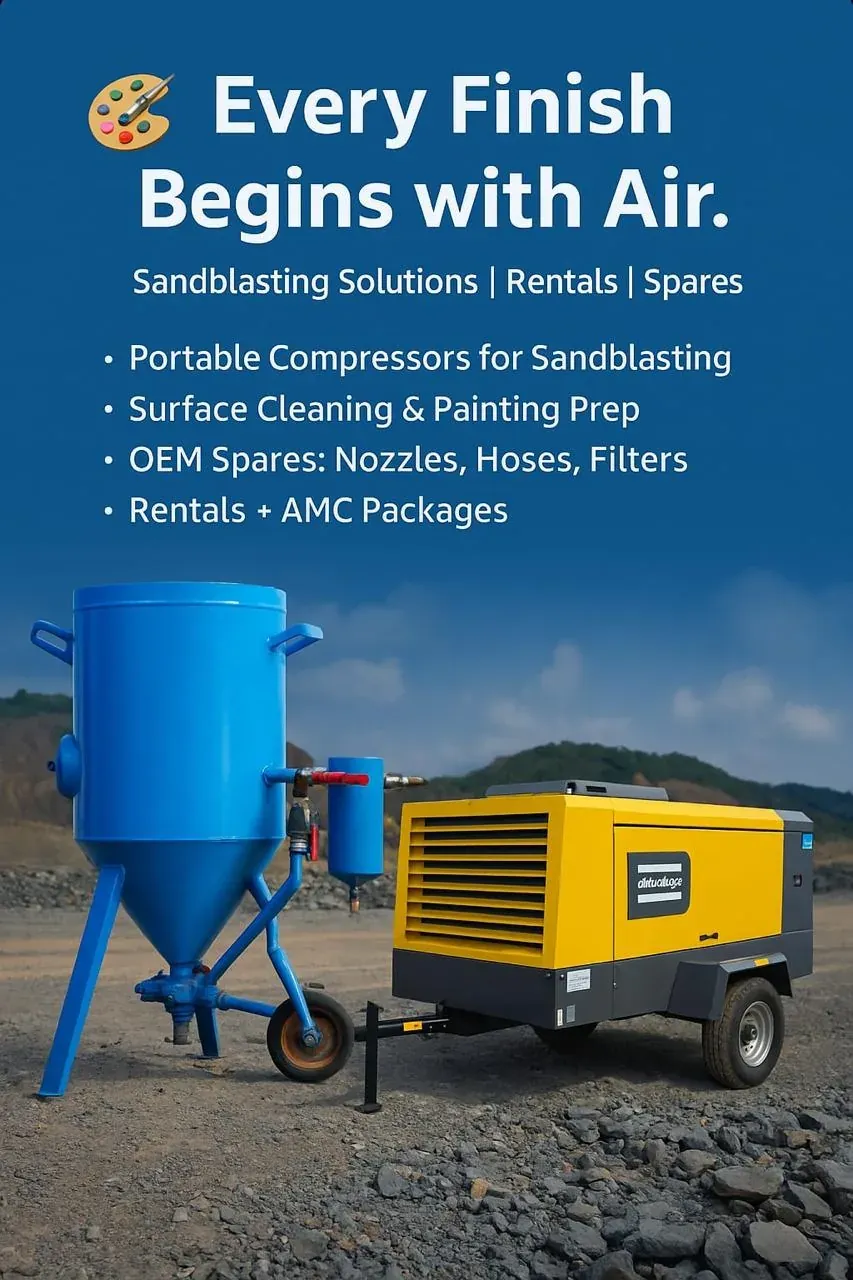
2. Controlled ownership
3. Exact blast machine
Record manufacturer, model, vessel/pot identity, verified permitted supply condition, inlet, control system, metering arrangement, nozzle range and accessories. Do not transfer limits or valve/control assumptions from another pot that appears similar.
4. Pressure-vessel boundary
A blast pot is pressure-containing equipment. Design, inspection, relief protection, operation and maintenance remain governed by exact equipment documentation, applicable site requirements and competent personnel.
5. Ratings
Compressor capability above the blast pot's permitted condition is not permission to expose the pot, hose, valves or accessories to higher pressure. Every component in the pressure path must remain within its verified limits.
6. Compressor versus pot inlet pressure
Compressor discharge can differ from pot inlet because aftercoolers, separators, dryers, filters, valves, manifolds, hose and couplings consume pressure. Verify the pressure at the interface required by the blast-equipment supplier.
7. Pot inlet versus nozzle pressure
Pot inlet pressure is not nozzle working pressure. Downstream valves, metering equipment, blast hose and nozzle path impose additional losses.
8. Flow requirement
Add only identified blast-equipment/control demands and documented auxiliaries. Do not substitute a generic reserve percentage for an actual load schedule.
9. Multiple pots
If several pots/operators share one source, define credible simultaneous operation. Installed outlets are not automatically simultaneous demand, but unverified diversity is equally unacceptable.
10. Compatible flow basis
Compare compressor capacity with blast demand on compatible reference and pressure bases.
11. Air-preparation objective
Air preparation should support equipment reliability, abrasive flow and the project surface-preparation requirement.
12. Aftercooling
Aftercooling can reduce air temperature and support condensate separation, but actual performance depends on package design, ambient condition and load. Its presence does not prove a particular dryness level.
13. Separation and drains
Separators and drains must suit actual flow and operating condition. Overloaded or poorly drained equipment can pass moisture downstream.
14. Drying
Where the project or abrasive system requires a defined dryness condition, select and verify drying accordingly.
15. Filtration
Filters can protect equipment or process requirements but add pressure loss. Include justified filtration and its operating pressure loss in the interface budget.
16. Condensate
Provide controlled draining and disposal under site requirements. Prevent unmanaged condensate from entering blast equipment or accumulating around the work area.
17. Main supply hose
Record hose identity, internal diameter, length, pressure rating, condition, route and connections. Long or undersized hose can consume pressure before the pot.
18. Hose and fitting compatibility
Every hose and fitting must be suitable for actual pressure, temperature and service. Similar-looking fittings can have different ratings. Improvised adaptors are not substitutes for verified components.
19. Couplings
Couplings can be restrictions and mechanical-integrity points. Verify compatibility, rating, condition and retention provisions required by equipment/site procedures.
20. Manifold
A common manifold should be assessed for credible total flow, internal passage, isolation, pressure rating, drains and maintainability. Outlet count alone does not establish capacity.
21. Avoid cumulative restrictions
Multiple small hoses, adaptors and couplings can create large cumulative loss. Where project design permits, carry bulk flow near the workfront before splitting to final connections.
22. Control architecture
Record whether blast controls are pneumatic, electro-pneumatic or another manufacturer-defined arrangement. Identify control supply separately from main blast flow where equipment documentation does so.
23. Remote/deadman control boundary
Operator blast controls are safety-critical equipment functions. Follow the exact manufacturer's instructions and authorised site procedure.
24. Protective functions
Do not bypass protective functions to overcome production delay or suspected control faults. Troubleshoot under approved procedures.
25. Isolation sequence
The supplied compressor safety foundation uses the general sequence isolate, depressurise, verify zero stored pressure, then intervene. The exact equipment/site procedure remains controlling.
26. Stopped does not mean depressurised
Stopping the compressor does not prove the blast pot, hose or downstream equipment is depressurised. Stored pressure can remain.
27. Relief protection
Pressure relief and vessel protection follow the exact equipment design and applicable requirements.
28. Compressor control interaction
Sustained blasting can keep a compressor heavily loaded; intermittent blasting can create cycling or pressure swings. Record control mode and observe pressure stability under real duty.
29. Parallel compressors
Where several compressors are paralleled, confirm compatible controls, isolation/check arrangements, pressure settings and load sharing. Do not simply add nameplate flows.
30. Portable package boundary
For portable packages include exact package condition, ambient/site effects where supported, fuel logistics and maintenance. Do not transfer capacities or settings from another model.
31. Electric package boundary
For electric packages confirm electrical supply and installation separately. Electrical suitability does not change the pot's pressure-flow requirement.
32. Worked example — pressure budget
Illustrative method only. Begin with the validated nozzle working condition and add measured or supplier-supported losses through blast hose/pot, source hose/manifold and treatment to establish the required source-side condition, without exceeding any component rating. No universal loss values are assumed.
33. Worked example — two-pot concurrency
Illustrative method only. Pot A serves demand QA and Pot B demand QB. If both blast simultaneously, source demand begins with QA + QB plus identified auxiliaries on compatible bases. If verified operation prevents overlap, document that evidence.
34. Worked example — restriction localisation
Illustrative only. Compressor discharge remains stable but pot inlet pressure falls during blasting. Measure across treatment, manifold, hose and couplings under flow. Correct the largest verified restriction before raising compressor pressure.
35. Worked example — treatment trade-off
Illustrative method only. A treatment component improves required air condition but adds pressure loss. Compare process need, delivered-pressure margin and source energy rather than bypassing treatment or automatically raising pressure.
36. Nozzle wear feedback
An interface adequate with a new nozzle can become pressure-limited as the nozzle wears. Include nozzle condition in diagnosis.
37. Media metering boundary
Abrasive metering is a blast-equipment/process function, not a compressor-flow control. Do not correct a metering fault solely by changing source pressure.
38. Moisture and media flow
Wet-media symptoms can originate from air condition, drains, ambient exposure, abrasive storage or equipment condition. Preserve evidence before adding treatment or changing pressure.
39. Slow pot pressurisation
Check source pressure-flow, inlet restriction, hose/couplings, valves, control state, leaks and exact equipment condition. Slow pressurisation is not automatically a small compressor.
40. Pot pressure good, nozzle pressure low
Focus downstream: metering/valves, blast hose, couplings, nozzle condition and verified nozzle demand. The pot gauge alone does not prove nozzle condition.
41. Pressure falls with second operator
Assess concurrency, common manifold restriction, source capacity, treatment loss and nozzle condition. Separate generation from distribution limitations.
42. Recurring water
Check aftercooling/separation performance, drains, ambient/seasonal condition, hose low points and treatment. A compressor-room separator may not control all downstream condensation.
43. Unstable remote control
Use manufacturer troubleshooting for the exact control system. Check documented control-air supply and physical condition without bypassing safety functions.
44. Excessive compressor loading
Compare actual nozzle demand, nozzle wear, leakage, simultaneous users and pressure setpoint. Worn nozzles or excess pressure can increase load.
45. Leakage
Inspect source hose, manifold, pot fittings, valves and control circuits under approved safe methods. Continuous leakage wastes capacity and distorts sizing conclusions.
46. Rental interface
A rental compressor must be integrated with the actual pot, treatment and hose arrangement. Confirm pressure-flow compatibility, ratings, treatment, controls, fuel/electrical needs and commissioning.
47. Long campaign
Track compressor hours, treatment condition, hose/coupling wear, nozzle condition, pot maintenance and control function. The interface can drift from commissioning condition.
48. Responsibility
Define ownership of compressor package, treatment, main hose/manifold, blast pot, controls, blast hose and nozzle. Split ownership without an interface register can leave restrictions or safety devices unmanaged.
49. Change control
A new nozzle, longer hose, different pot, added operator, changed treatment train or replacement coupling can alter the interface. Update the checklist and demand basis.
50. Commissioning documentation
Confirm equipment identity, ratings, manuals, connection plan, treatment, nozzle schedule, control architecture and responsible persons before pressurisation under the project procedure.
51. Commissioning physical interface
Verify hoses, couplings, manifold, valves, drains and treatment are installed and suitable for the documented duty.
52. Commissioning controls
Verify blast controls and shutdown behaviour using the manufacturer/site procedure.
53. Commissioning dynamic pressure
Operate the governing nozzle combination and record source pressure, pot inlet condition and downstream/nozzle condition using approved methods.
54. Commissioning air preparation
Verify drains and required air condition under representative load and ambient condition. Record treatment differential pressure where relevant.
55. Repeated operation
Observe stable sustained/repeated blasting, not only initial pressurisation. Record pressure decay, water carryover, control instability or abnormal compressor cycling.
56. Acceptance
Surface-quality acceptance and pressure-vessel compliance remain with their respective project requirements.
57. Required asset purpose
The Blast Equipment Interface Checklist establishes clear responsibility across the compressor-to-nozzle chain so pressure-vessel integrity, air preparation, distribution and controls are not lost between compressor supplier, blast contractor and site team.
58. Checklist identity
Record compressor/package, treatment equipment, manifold, main hose, blast pot make/model/asset ID, control system, blast hose and nozzle.
59. Checklist ratings
Record verified permitted pressures/temperatures and source documentation for each pressure-containing component. Do not infer ratings from appearance.
60. Checklist demand
61. Checklist preparation
Record aftercooling/separation/drying/filtration functions, drains, pressure loss, ambient basis and required air condition.
62. Checklist controls/safety
Record manufacturer control architecture, isolation points, relief/protection identification, authorised test-procedure reference and responsibility. Do not include bypass instructions.
63. Checklist distribution
Record manifold, hose IDs/lengths/ratings, couplings, route, pressure measurement points and observed dynamic losses.
64. Checklist responsibility
Assign compressor, treatment, hose/manifold, pot/vessel, controls, nozzle, condensate and commissioning ownership. Record unresolved interfaces.
65. Checklist acceptance
Record dynamic source/pot/nozzle conditions, air-preparation result, governing concurrency, control-verification reference, open items, approval and revision.