
What the image library is for
Most people who contact us about a compressor are trying to describe something they can see but cannot name: a valve on top of the separator tank, a gauge that reads oddly, a hose that keeps failing, a canopy door that will not close. A clear, correctly captioned picture closes that gap faster than any description.
Posters and field graphics
Reddy Compressors graphics




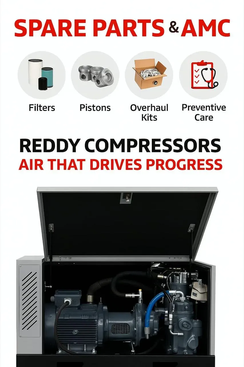

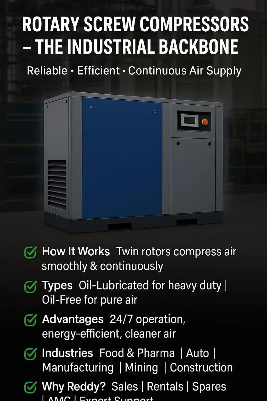

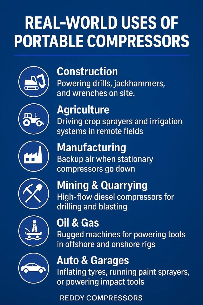


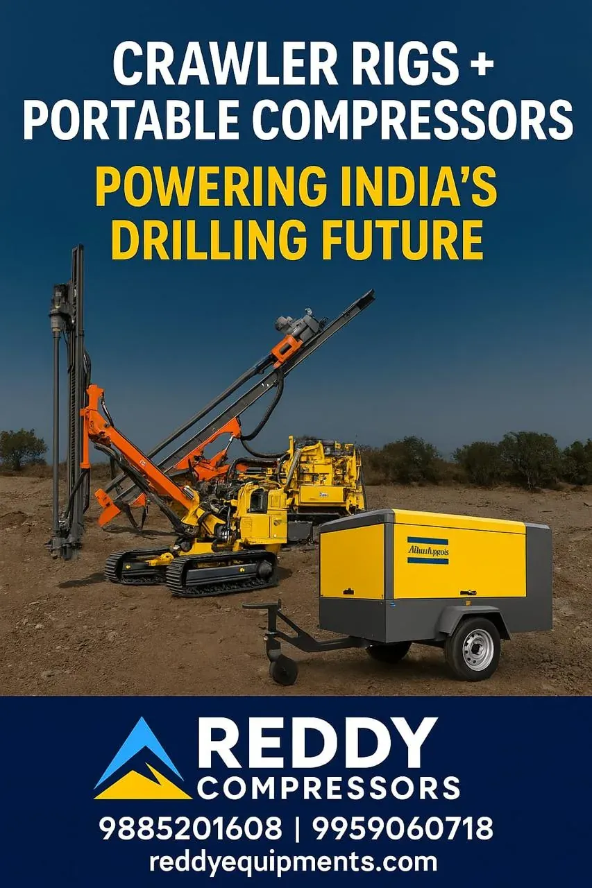

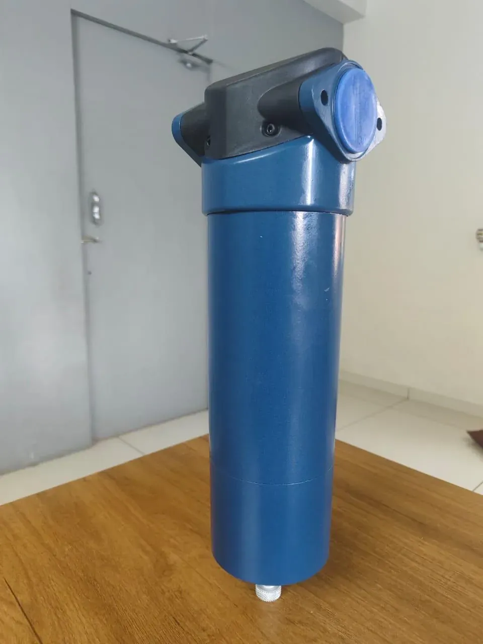


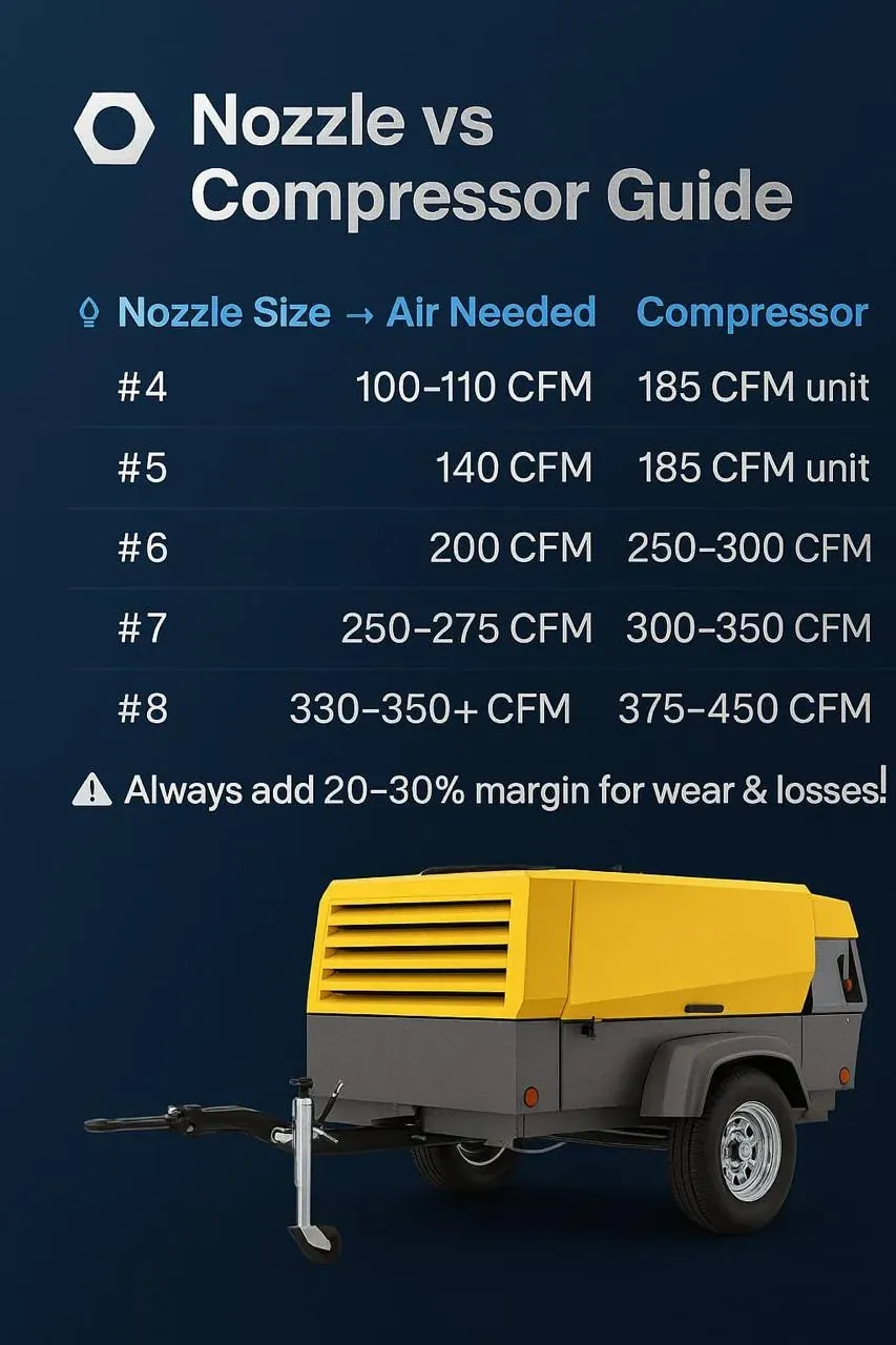
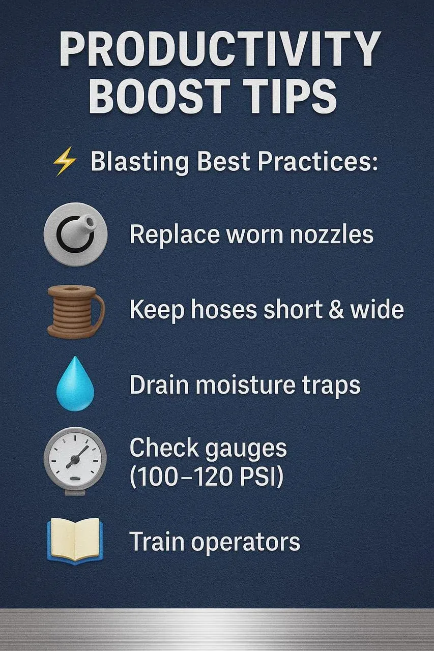

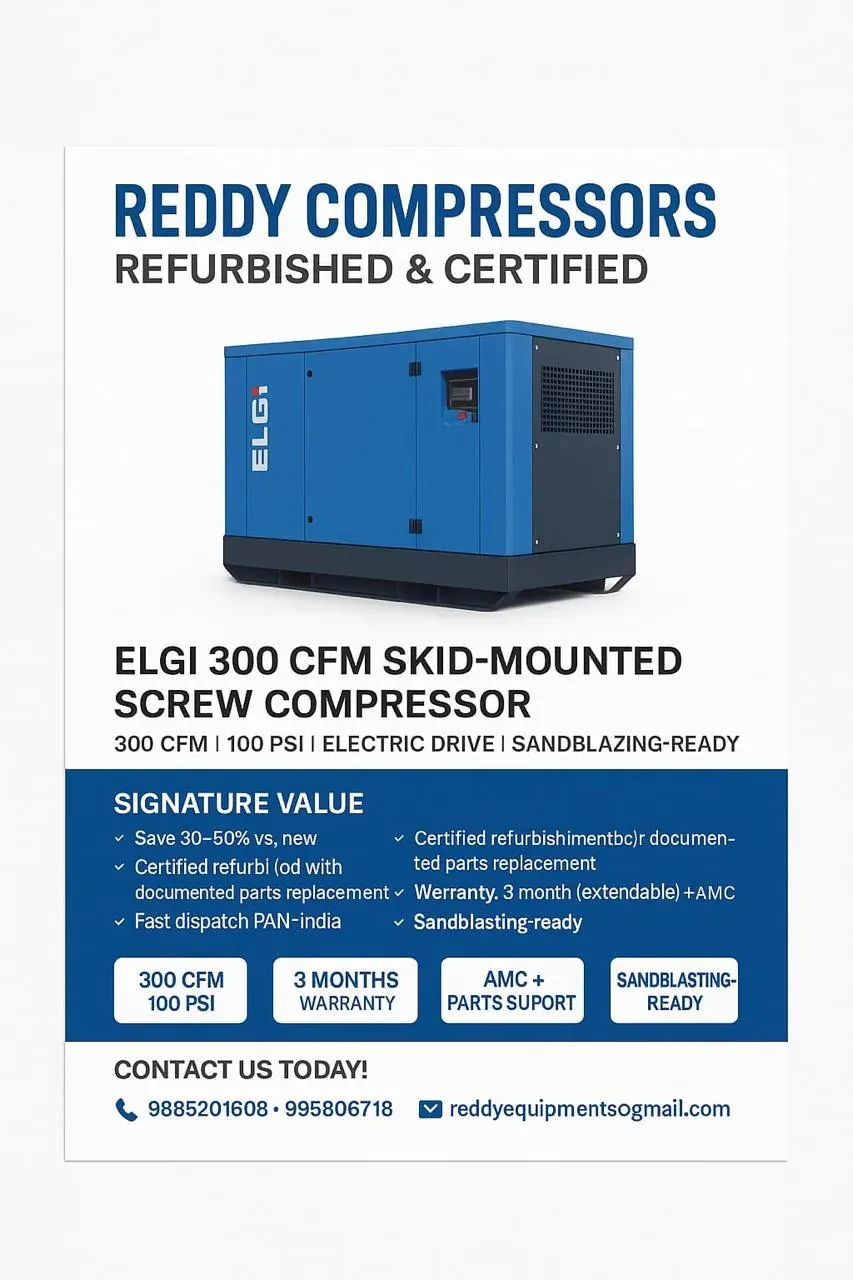
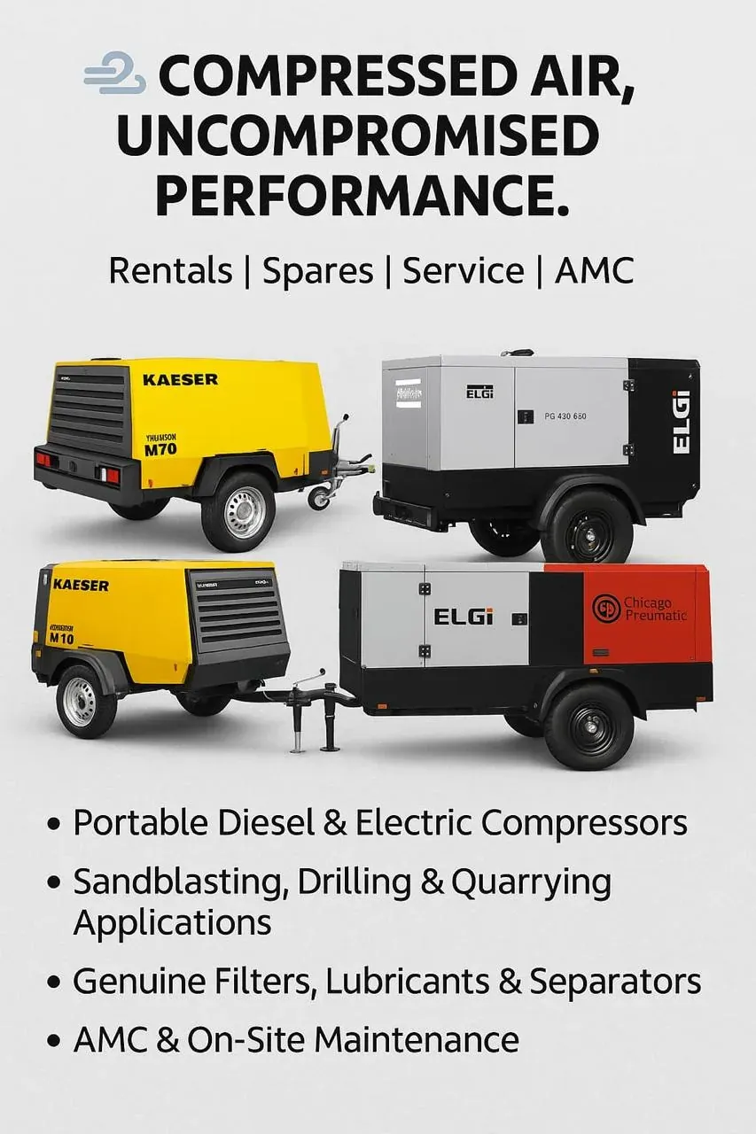


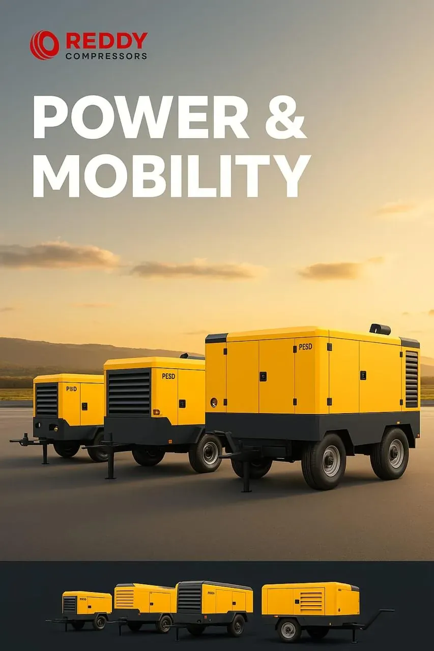

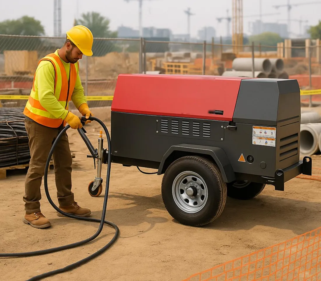
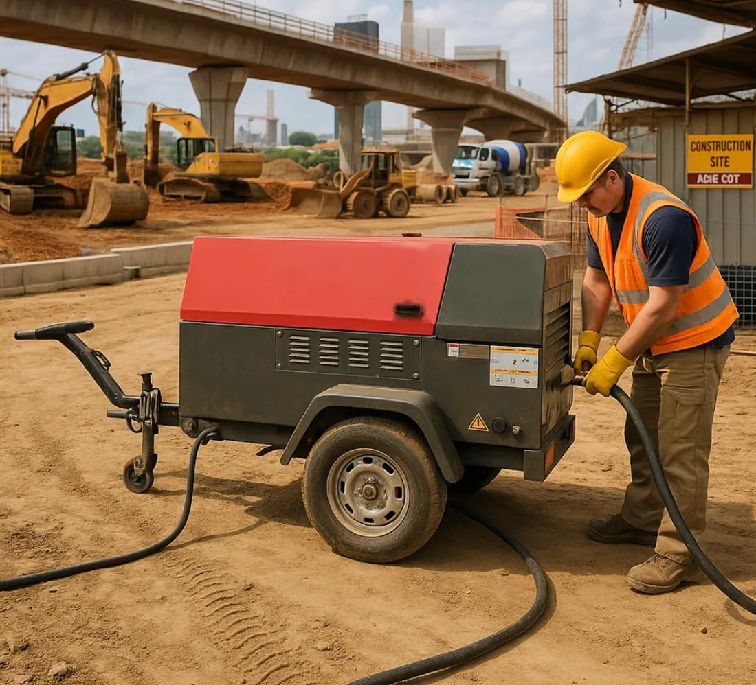

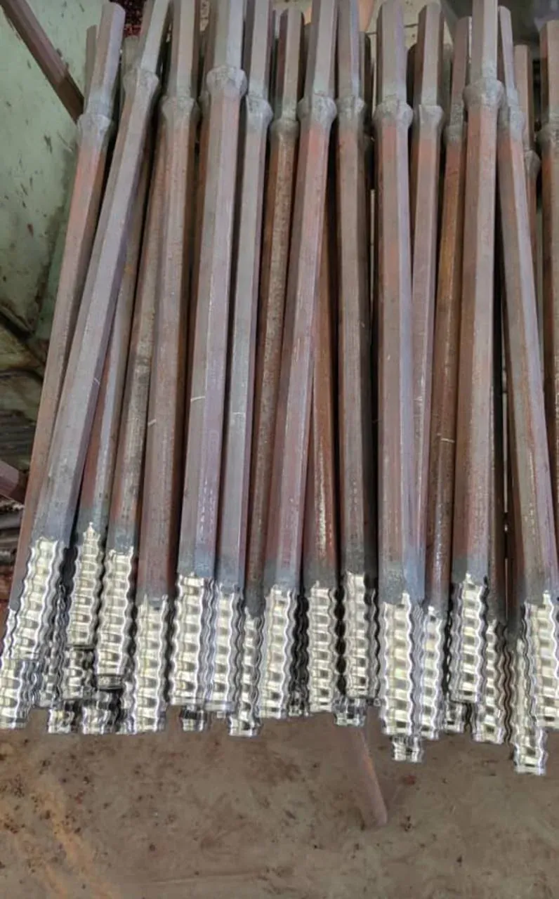
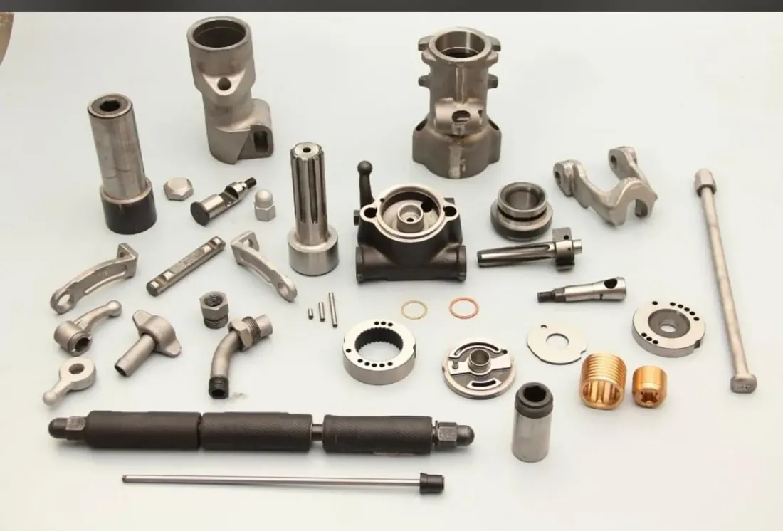
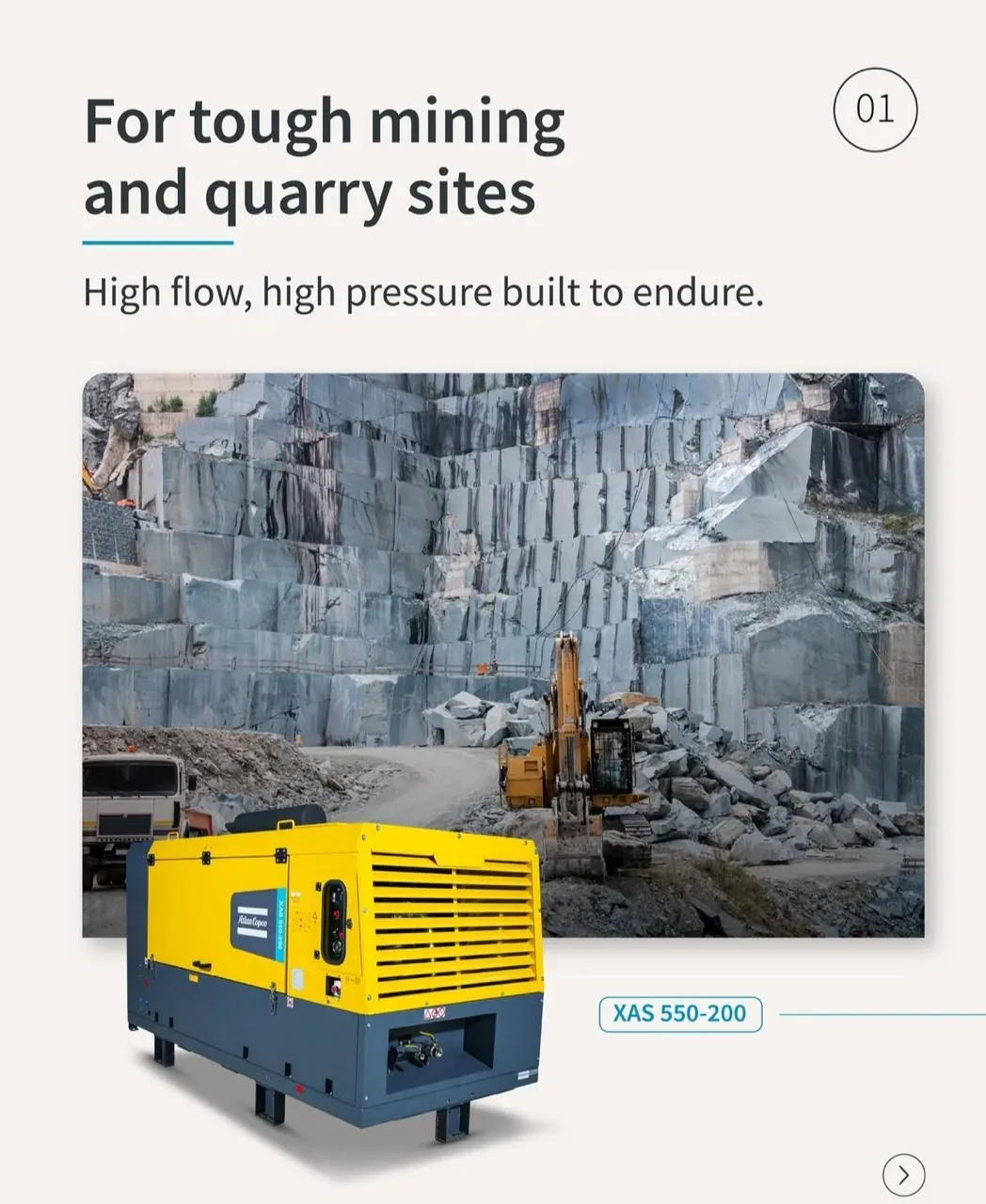
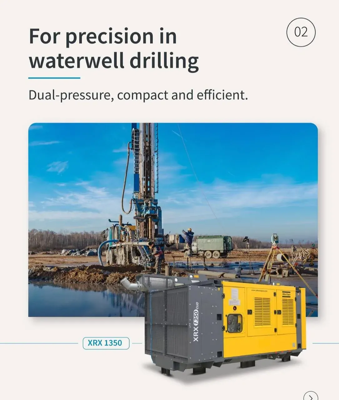


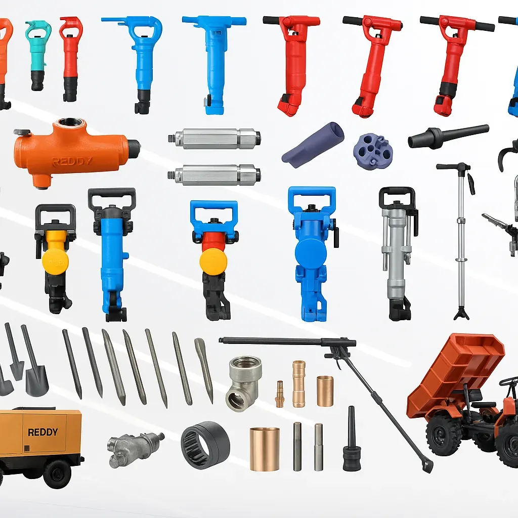


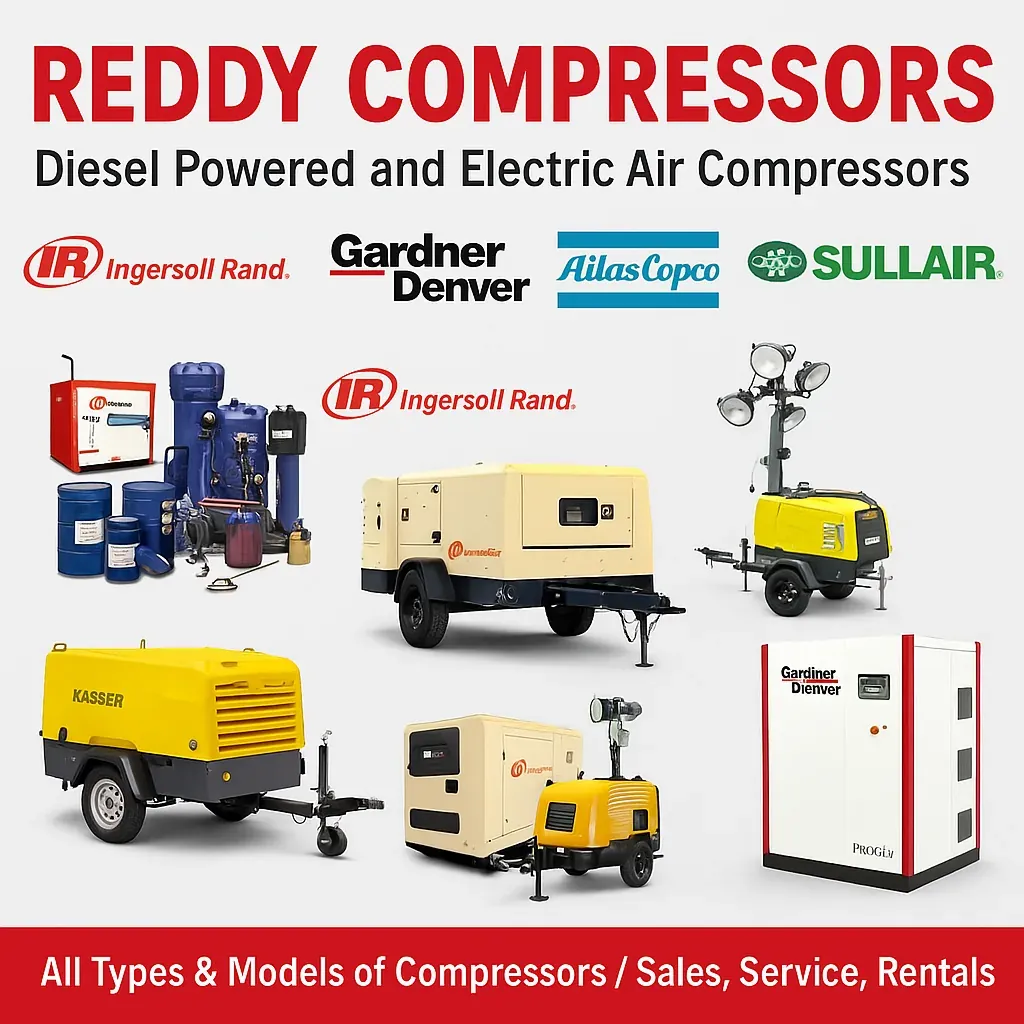

Across brands
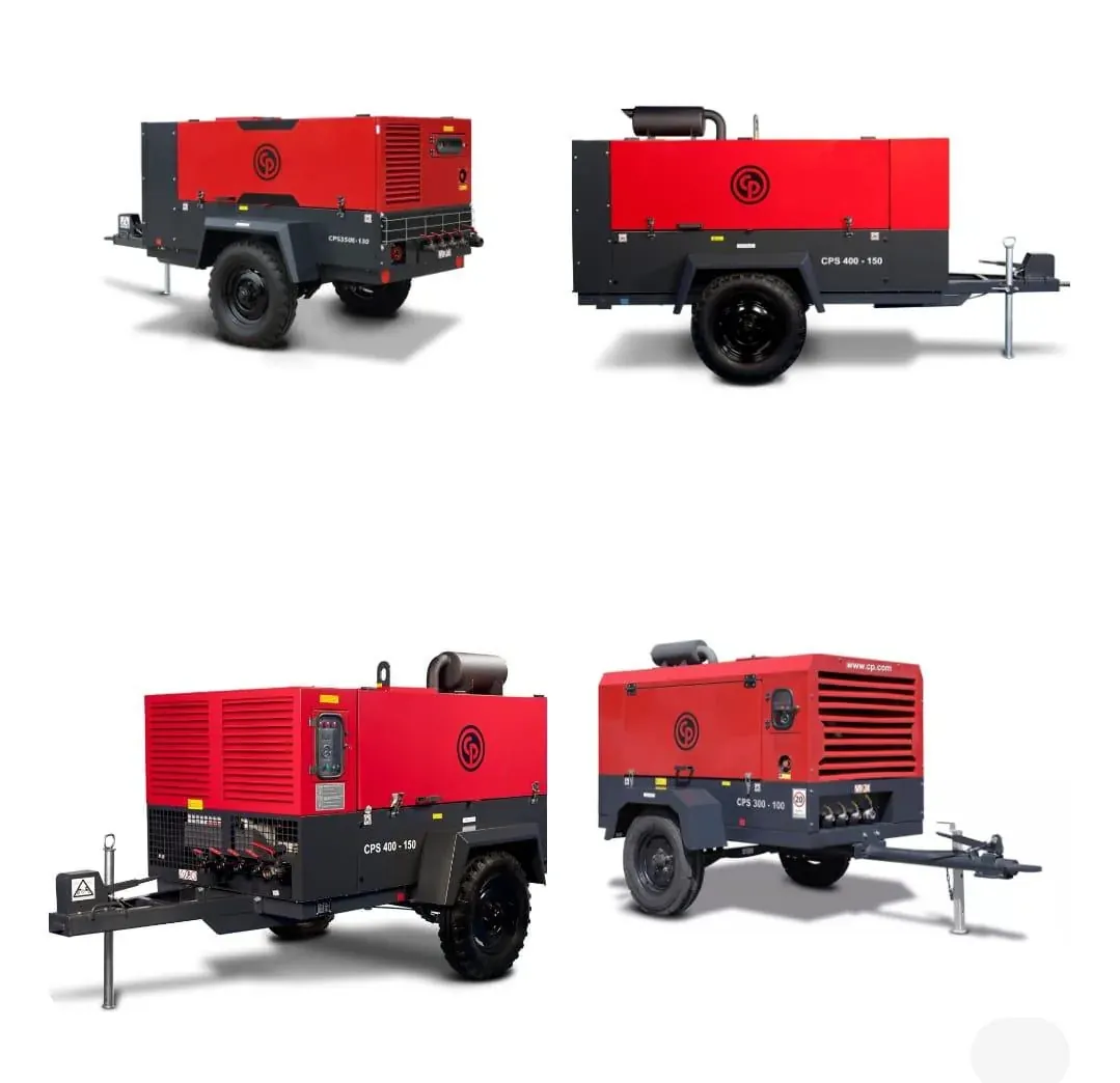
Models we supply and service
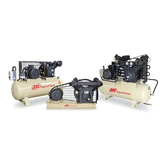
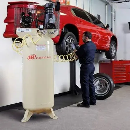
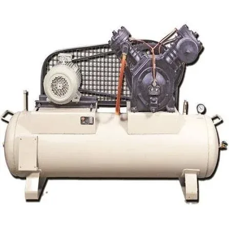
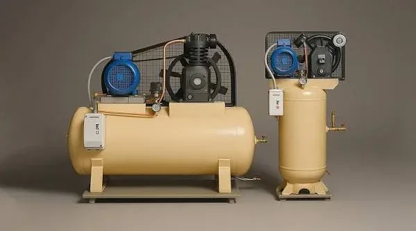
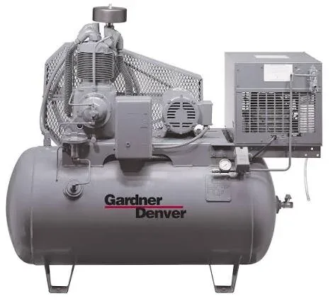
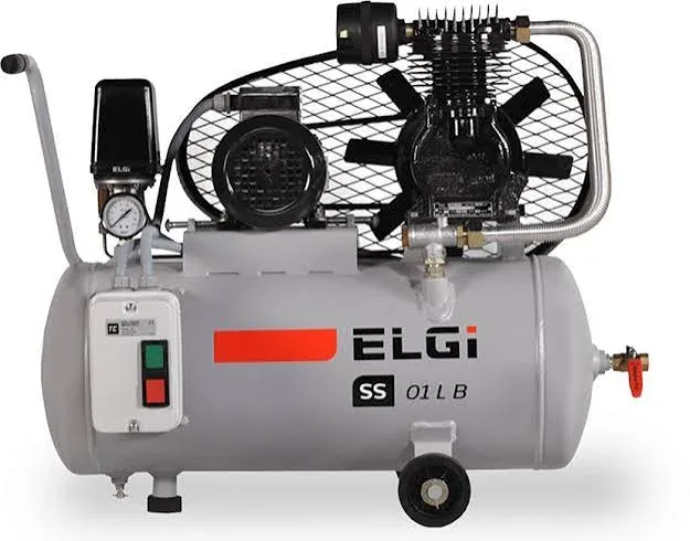
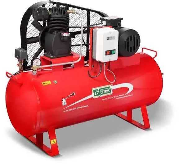
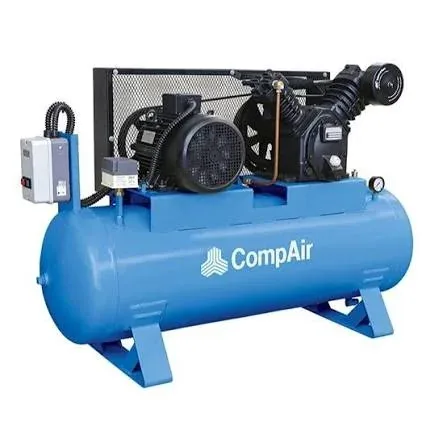
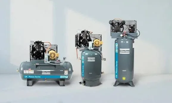
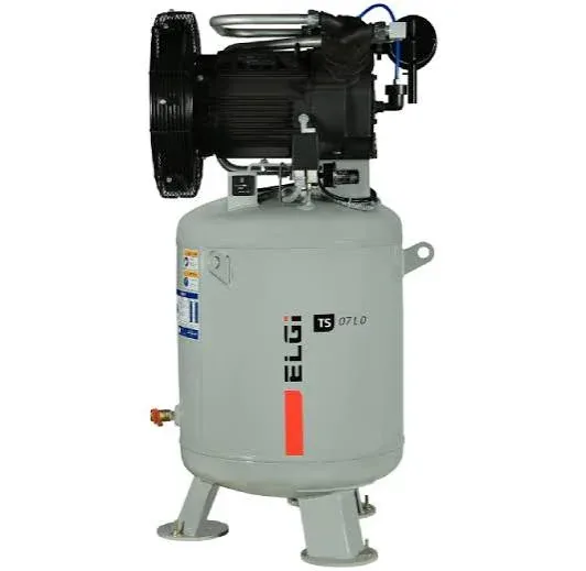
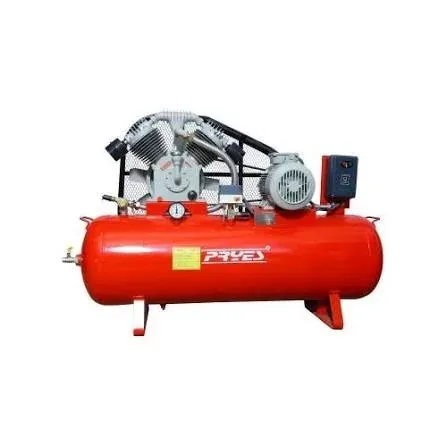
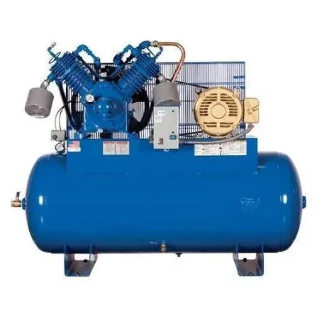
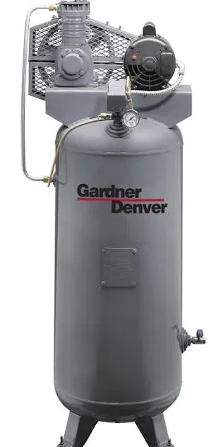
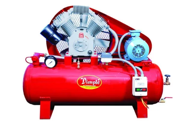
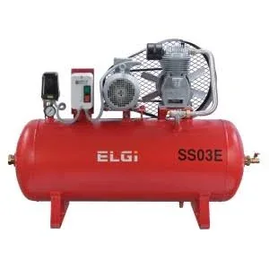
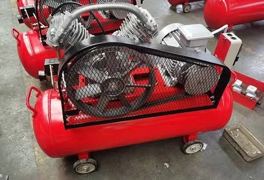
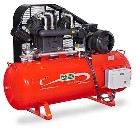
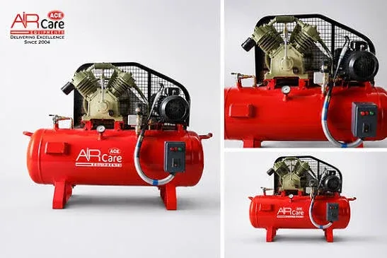
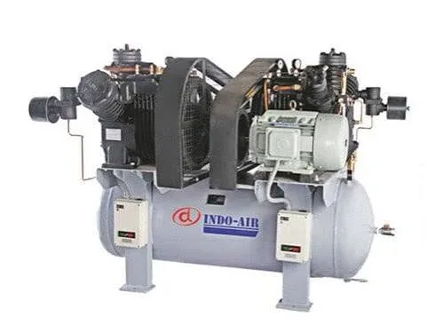
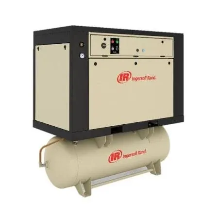
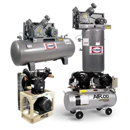
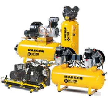
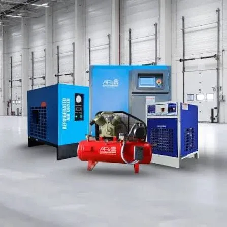
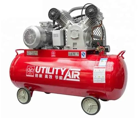
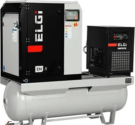
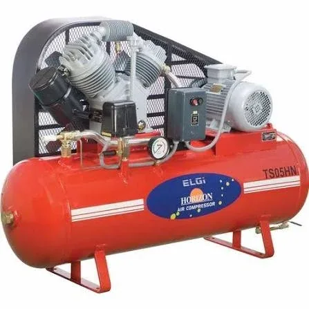
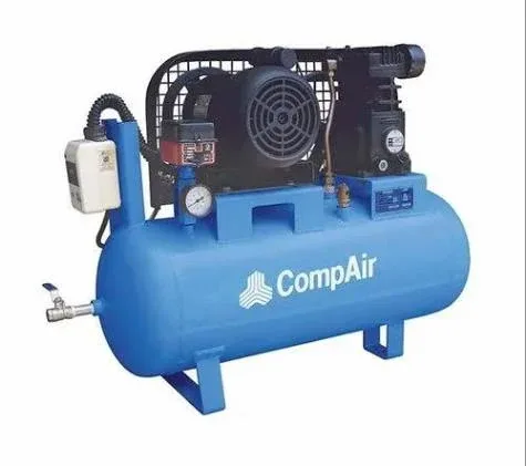
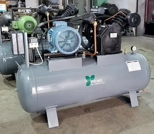
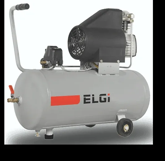
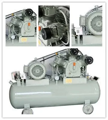
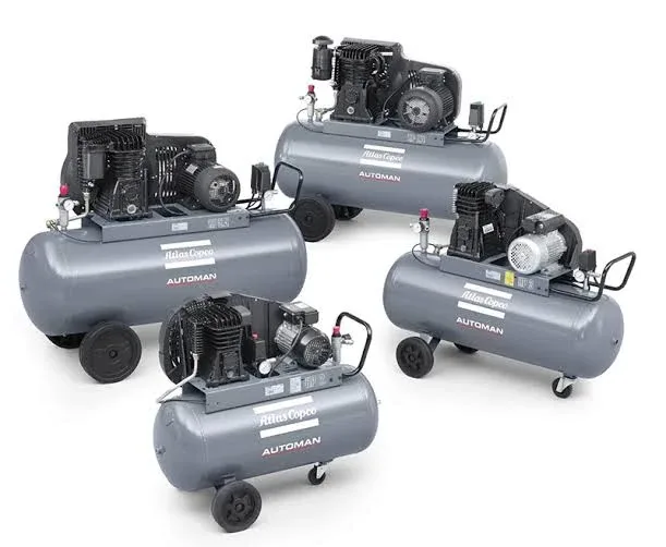
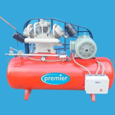
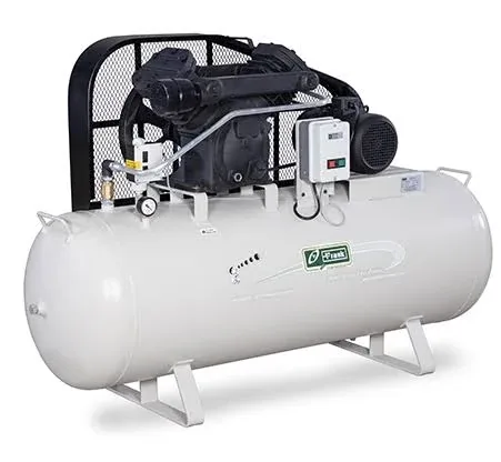
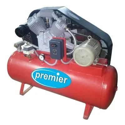
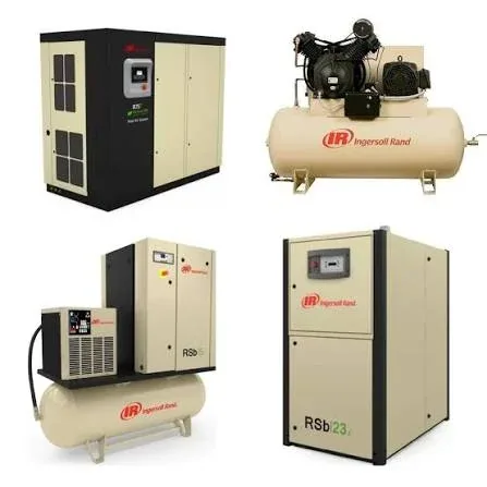
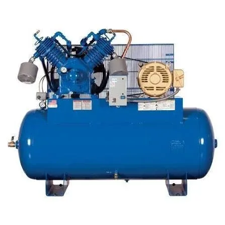
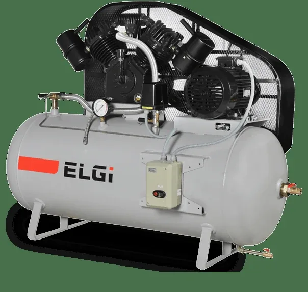
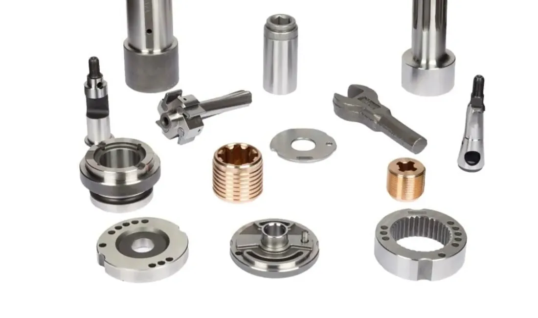
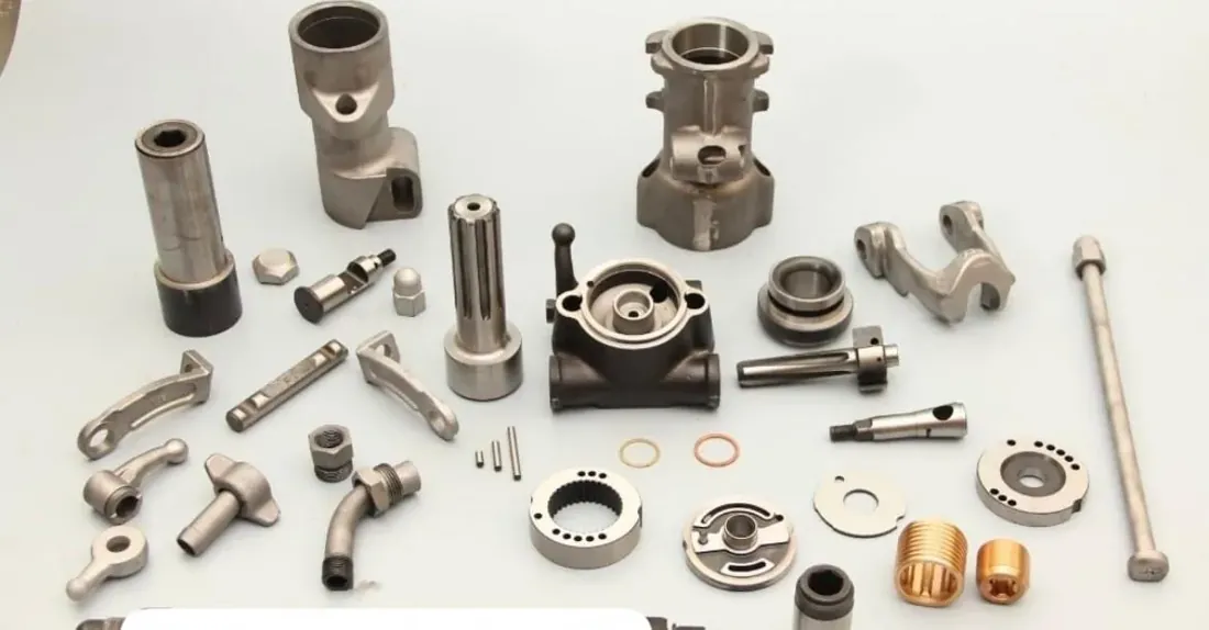
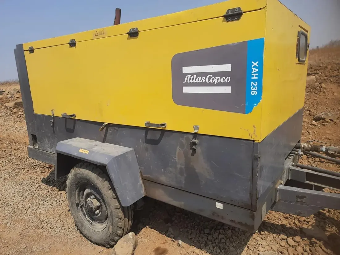
Manufacturer product images, shown to identify machines we sell, service and support. Brand names are trademarks of their owners.
The library is organised so that a maintenance technician, a plant engineer, a buyer and a site supervisor can each find what they need:
- Technicians can tell an inlet valve from a minimum-pressure valve, or an oil filter from an air/oil separator element.
- Engineers can follow the air and oil flow path through a screw package or a dryer.
- Buyers can see the practical differences between a stationary screw package, a portable diesel unit, a tractor-mounted piston compressor and an oil-free machine.
- Site teams can see how hoses, manifolds, aftercoolers and moisture separators are laid out on a rental or project installation.
Images support the technical articles; they do not replace them. Each caption links to the page that explains selection, sizing, service or safety in full.
How each image is labelled
A picture of a compressor can mislead as easily as it can inform. Two machines from different makers may look almost identical from outside and differ completely in airend, rating and control logic. For that reason every image carries one of these labels:
| Label | What it means | What you can rely on |
|---|---|---|
| Our photograph – identified equipment | Taken by our team on equipment we sold, hired, serviced or overhauled, with the make and type confirmed | The equipment type and the components named in the caption |
| Our photograph – equipment family | Real equipment where the exact model is not confirmed or not relevant | The general type (for example an oil-injected screw package) and its main parts |
| Generic example | A representative view used to explain a type or component | The concept only; not any particular brand or model |
| Diagram or illustration | A drawing of a flow path, layout or principle | How the system works in principle; real arrangements vary by maker |
Brand names visible in photographs belong to their owners; showing a machine does not mean we are that brand’s authorised distributor. Reddy Compressors is an independent multi-brand specialist.
Inside a rotary screw package: what you are looking at
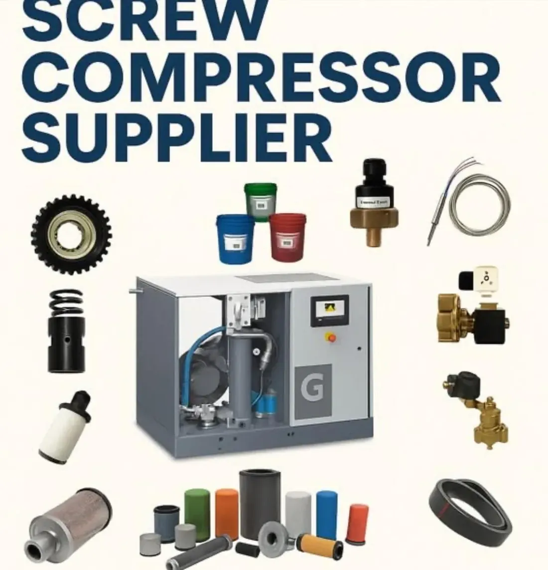
The oil-injected rotary screw compressor is the most common industrial machine in India, from small workshop units to large plant-air packages. Once the canopy panels are off, most makes share the same building blocks, even though their position and appearance differ.
| Component | Where to find it | What it does | What a photo can and cannot show |
|---|---|---|---|
| Inlet air filter | At the air intake, usually high on the package | Stops dust entering the airend | Shows type and fitting; not how clogged the element is |
| Inlet (suction) valve | Between filter and airend | Opens to load and closes to unload or modulate | Shows the valve body; not whether it seals or sticks |
| Airend | Driven by the motor through a coupling, belts or gears | Pair of helical rotors that compress the air | Shows the casing and drive; never internal rotor or bearing condition |
| Separator tank | Pressure vessel after the airend | Separates most of the oil from the air and holds the oil charge | Shows sight glass and fittings; oil level must be read with the machine in the correct state |
| Air/oil separator element | Inside or on top of the separator tank | Removes the fine oil mist before air leaves the package | Shows the element type; not its pressure drop or carry-over |
| Minimum-pressure valve | Outlet of the separator tank | Holds tank pressure for oil circulation and stops back-flow | Shows position; not set point or seat condition |
| Thermostatic valve and oil filter | In the oil circuit | Keeps oil temperature in range and filters it | Shows the parts; not whether the thermostat opens correctly |
| Oil cooler and aftercooler | Combined cooler block with fan, or water-cooled exchangers | Cool the oil and the discharge air | Shows fouling on the fins very clearly |
| Controller and starter | Electrical cabinet and display | Load/unload, pressure bands, protections and fault history | Shows readings and fault codes at that moment |
A healthy oil-injected screw package typically runs with a discharge temperature of about 75–95 °C. A photograph of the display showing a figure well above that, together with a picture of dusty cooler fins, is one of the most useful images you can send us in an Indian summer.
Recognising machine types from their appearance
Buyers often ask what separates one type from another when they look similar on a brochure page. The table below lists the visual cues our engineers use, and the limits of each.
| Type | Typical visual cues | Easily confused with |
|---|---|---|
| Stationary screw package | Rectangular acoustic canopy, cooler grille, control panel, fixed base, often with a dryer or receiver alongside | Integrated compressor-dryer packages and some oil-free units |
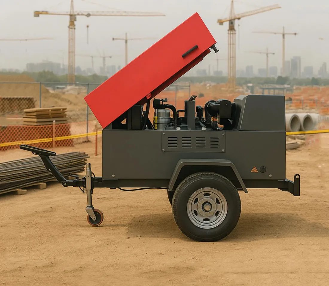
| Portable diesel screw compressor | Wheeled chassis, towbar, lockable canopy doors, fuel filler, service valves on one side | Mobile generators of similar size |
| Reciprocating (piston) compressor | Finned cylinders, belt guard, flywheel, horizontal or vertical receiver | Tractor-mounted PTO compressors |
| Tractor-mounted compressor | Piston compressor on a tractor or trolley, driven through the power take-off | Small trailer-mounted piston units |
| Oil-free screw or tooth compressor | Larger package for the same output, intercooler, no oil separator tank | Oil-injected packages with integrated filtration |
| Centrifugal compressor | Large gearbox with impellers, intercoolers between stages, big inlet guide vanes | Large blowers |
| Roots or screw blower | Low-pressure package with large inlet silencer and outlet pipe | Low-pressure screw compressors |
No photograph establishes free air delivery, pressure rating or condition. Those come from the nameplate, the maker’s data and, where it matters, a measured test.
Portable diesel compressors: outside and inside
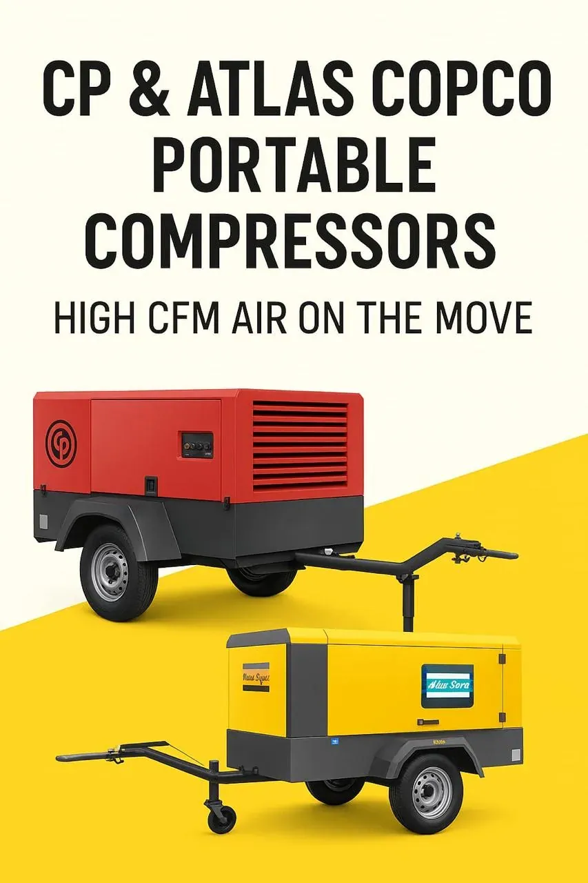
Portable diesel units in the 185–600 cfm range are a large part of our sales and hire work, so the library covers them in detail. External views show the towbar and running gear, lifting eye, canopy doors, fuel filler, service valves and the instrument panel. Internal views show the diesel engine, the airend and drive, the combined radiator and oil cooler, the separator tank, the inlet filters for engine and airend, and the safety shutdown switches.
Captions explain the protections most site staff meet in practice: high discharge temperature, low engine oil pressure and high coolant temperature shutdowns. In summer heat of 40–45 °C, and above 45 °C on open sites, and in heavy dust, a blocked cooler or a choked air filter will trip these long before anything breaks, and a picture of the cooler core usually tells the story.
Air treatment, receivers and distribution
Images of air treatment explain what each stage looks like and where it sits:
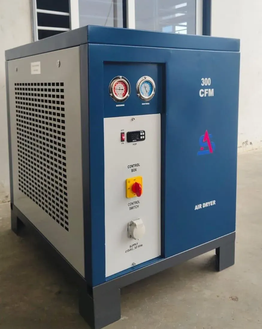
- Refrigerated dryers, which typically deliver a pressure dew point of about +3 °C, with their condenser grille and drain.
- Desiccant (adsorption) dryers with twin towers, typically used for pressure dew points of −20 °C or −40 °C.
- Coalescing and particulate filters, their differential pressure indicators and drains.
- Air receivers with safety valve, pressure gauge, drain valve and inspection opening.
- Ring mains, drops taken from the top of the header, isolation valves and point-of-use filter-regulator-lubricator sets.
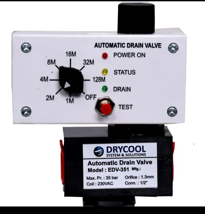
Pictures of corroded drains, water in a filter bowl or an undersized drop leg are often the first evidence of an air-quality problem; the dryer and treatment pages explain what to do next.
What a photograph cannot tell you
We are careful not to read more into an image than it contains. A photograph cannot confirm:
- the exact model or variant, because many makers use similar canopies and panels across a range;
- internal condition of rotors, bearings, valves or seals;
- rated flow, pressure or motor power, unless the nameplate is legible;
- whether a part from one machine fits another that looks the same;
- whether a pressure vessel or safety valve is fit for continued service.
Where an identification is uncertain, the caption says so. When you send us photographs, we treat them the same way: they help us ask the right questions, and we confirm parts and faults from the nameplate, serial number and, if needed, a site visit before quoting.
How to photograph your compressor for us
Good photographs shorten diagnosis and parts identification. Never open panels on a running machine, remove guards or loosen anything under pressure to take a picture. Follow your site’s isolation procedure.
- Take one overall view of the machine from each side, showing the surroundings and ventilation.
- Photograph the nameplate square-on and in focus so make, model, serial number, pressure and motor rating are readable.
- Photograph the controller display showing pressure, temperature, running hours and any fault code or alarm history.
- Photograph the part concerned in place, then the removed part beside a ruler, including any part number stamped or printed on it.
- Show the condition that worries you: oil leak, water in filters, damaged hose, dusty cooler or discoloured pipework.
- Add a short note of when the problem started, what changed and the operating pressure you need.
How Reddy Compressors helps
From our office at Tarnaka, Secunderabad, our team of more than 20 service engineers and technicians sells, rents and services compressors of ELGi, Atlas Copco, Ingersoll Rand, KAESER, Chicago Pneumatic and many other makes. We use your photographs and nameplate details to identify spare parts and confirm fit before quoting, to triage breakdowns before a visit, and to suggest whether repair, overhaul, a used machine or a hire unit makes most sense. Service visits cover all of Telangana and Andhra Pradesh, and we supply compressors, rentals and spare parts across India.
What to send us
- Clear photographs of the nameplate, the controller display and the part or problem area.
- Make, model, serial number and running hours.
- Required working pressure in bar or psig and the air demand you expect.
- Site location and whether the machine is stationary, portable or on hire.
- Your name, company and a phone or WhatsApp number.
Frequently asked questions
How can I identify the parts of my air compressor?
Start with the nameplate, which gives make, model and serial number, then compare what you see with a labelled diagram of the same machine type. Most screw packages share an inlet filter, inlet valve, airend, separator tank, minimum-pressure valve, oil filter, thermostatic valve and cooler. If you are unsure, send us photographs of the nameplate and the area concerned and we will identify the part and confirm fit before quoting.
Can you tell the compressor model from a photo?
Sometimes the type and maker are obvious, but the exact model and variant usually are not, because many ranges share the same canopy and panel. We rely on a readable nameplate and serial number to confirm the model. A photograph is excellent for showing condition, layout and faults, but it does not establish rated flow, pressure or which spare part will fit.
What is the difference between an air/oil separator and an oil filter?
The oil filter cleans the oil that lubricates and cools the airend, removing wear particles and degraded additives. The air/oil separator element sits in or on the separator tank and strips the fine oil mist out of the compressed air before it leaves the package. Both are routine service items, and a blocked separator raises pressure drop and power use while a failed one sends oil downstream.
Why does my compressor have so many valves on the separator tank?
The tank usually carries a safety valve, a minimum-pressure valve, a blow-down or vent valve, an oil fill point, a sight glass and sometimes a pressure switch or sensor. Each has a distinct job: protection, maintaining oil circulation pressure, venting on stop, and allowing oil checks. Never adjust or remove the safety valve; any change to pressure settings needs a competent engineer and the maker’s data.
What photos should I send for a compressor breakdown?
Send the nameplate, the controller display with the fault code and running hours, an overall view of the machine and its ventilation, and a close-up of any leak, damage or warning light. Add a one-line description of what happened just before the stop. These usually let our engineers decide whether the fault can be talked through by phone, needs a visit, or needs a hire compressor meanwhile.
Can I use images from your library on my own website?
Please ask us first. Some images are our own and others are used with permission, and visible brand names and trademarks belong to their owners. We are happy to discuss use for training or internal documents.
Related pages
Technical content reviewed by D. Srinivas Reddy, Managing Partner and service engineer, Reddy Compressors. Last updated 17 October 2026. How our engineering content is reviewed.