
What the drill string has to do
In DTH drilling the drill string is both a mechanical member and an air pipe. At the same time it must:
- Carry its own weight and the hammer, and transmit feed and pullback force.
- Transmit rotation torque from the rotary head to the bit.
- Survive bending, vibration and the shock of the hammer working below it.
- Keep every threaded joint tight and sealed through repeated make-up and break-out.
- Deliver compressed air to the hammer with as little loss as possible.
- Leave enough annular space, but not too much, for air to lift cuttings to the surface.
A weakness in any one of these shows up as slow drilling, poor hole cleaning, a stuck or lost string, or a compressor that seems too small. That is why the air path and the mechanical path are best reviewed together.
The air path, piece by piece
| Component | What can go wrong | What we check |
|---|---|---|
| Compressor discharge valve and manifold | Partly closed or restricted valve, damaged seat | Valve fully open, pressure at outlet while drilling |
| Main air hose | Bore too small for the flow, excessive length, kinks, internal delamination | Hose bore and rating, length, condition, routing out of direct sun where possible |
| Couplings and whip-checks | Leaking seals, worn claws, missing safety restraints | Seals, locking pins, whip-check cables on every pressurised joint |
| Lubricator | Wrong oil, wrong feed rate, empty tank | Hammer oil grade and feed rate as the hammer maker specifies |
| Rotary head swivel | Worn seals leaking air, restricted bore | Leakage at the swivel, pressure before and after |
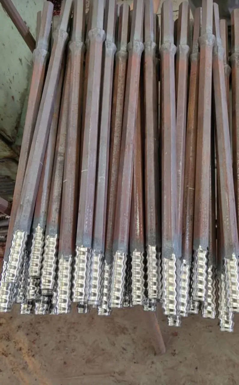
| Drill pipe and threads | Thread wear, damaged shoulders, leaking joints, internal scale or debris | Thread gauge, shoulder condition, bore clear, joint leakage |
| Adapters, subs and check valve | Wrong thread combination, worn check valve letting water and cuttings back up | Matching threads, check valve condition |
The hose and connection side is covered in more detail in air hoses and rig connections.
How much pressure is lost before the hammer?
Pressure falls along the air path because of friction in hoses and pipe and local losses at every coupling, bend, valve and swivel. For a straight length, engineers use the Darcy–Weisbach relationship: Δp = f × (L ÷ d) × (ρv² ÷ 2), where f is the friction factor, L the length, d the internal diameter, ρ the air density and v the velocity. Because compressed air is dense at high pressure, and its velocity rises as the bore narrows, a hose or pipe that is one size too small can cost a surprising amount of pressure.
Two practical points matter more than the formula:
- Loss rises roughly with the square of velocity, so doubling flow through the same hose increases loss about fourfold.
- Over long lengths or with large pressure drops, air expands and speeds up, so simple calculations underestimate the loss; measurement is more reliable.
The simplest test is two gauges: one at the compressor outlet and one at the swivel or rig inlet, both read while drilling. The difference is the surface air-path loss. A large difference points to hoses, couplings or the swivel rather than the compressor.
Drill pipe geometry and the annulus
The pipe’s outside diameter sets the annular space for the return flow. For a hole of diameter D and a pipe of outside diameter d, the annular area is A = π/4 × (D² − d²). For a given air flow, a smaller annulus gives a higher upward velocity and better cuttings lift; a larger annulus gives slower air and poorer cleaning.
Worked example: a 165 mm hole drilled with 114 mm pipe gives an annular area of about π/4 × (0.165² − 0.114²), roughly 0.0112 m². With 89 mm pipe in the same hole, the area grows to about 0.0152 m², around a third more, so the same air moves more slowly up the hole. These are geometry figures only; they do not size the compressor on their own.
The internal diameter matters too. A small bore increases internal pressure loss, while a thick wall adds weight. Wall thickness, joint design and steel grade are product-specific, so use the pipe maker’s data for the actual pipe, not a nominal size or a typical label. See annular velocity and cuttings transport and borehole cleaning.
Mechanical loads: weight, torque, bending and threads
Simple calculations help understand the loads, but they cannot rate a real drill string. As an illustration, a plain steel tube of 102 mm outside and 76 mm inside diameter has a wall of 13 mm, a steel area of about 0.0036 m² and a mass of roughly 28.5 kg per metre, before tool joints are added. Multiply by depth and the hanging weight grows quickly, which is why feed and pullback capacity and hoisting checks matter at depth.
The real limits usually sit at the threaded joints, not the pipe body:
- Threads and shoulders concentrate stress and see the highest fatigue loading from hammer shock and rotation.
- Bending in a curved or deviated hole adds cyclic stress each revolution, which drives fatigue cracking.
- Under-torqued joints leak air and loosen; over-torqued joints can gall or crack.
- Mixed pipe from different makers or batches may look compatible but not seal or carry load properly.
Use the maker’s make-up torque, thread type and rating for the actual pipe and adapters. Theoretical stress or buckling formulas for ideal tubes do not give a field rating for a confined, curved, vibrating drill string.
Inspection and wear checks
- Clean threads and inspect for galling, cracks, flattened crests and damaged shoulders.
- Check thread wear with the correct gauge, and pin and box shoulders for flatness.
- Check pipe straightness by rolling or sighting along it; bent pipe causes vibration and hole deviation.
- Measure outside diameter at wear points, especially near joints in abrasive formations.
- Look inside the bore for scale, rust, mud or debris that could reach the hammer.
- Apply the right thread compound and protectors before storage and transport.
- Record each pipe’s identity, hours or metres drilled and findings, so worn pieces are retired before they fail.
Keeping these records helps with borewell rig reliability and drilling records.
Symptoms and where to look
| Symptom | Likely air-path or string cause |
|---|---|
| Good pressure at compressor, weak hammer | Hose too small or long, leaking couplings, swivel leak, leaking pipe joints |
| Air bubbling at the surface around the casing or pipe joints | Leaking threads or damaged shoulders |
| Hammer stops after rod change | Water and cuttings back-flowing through a worn check valve; debris entering an open pipe |
| Poor hole cleaning with ample air | Pipe too small for the hole, giving a large annulus; water inflow; bit worn |
| Rotation torque high or erratic | Bent pipe, hole deviation, cuttings building up around the string |
| Repeated thread failures | Wrong make-up torque, mixed pipe, fatigue from bending, worn shoulders |
For compressor-side checks see borewell compressor performance diagnostics.
Depth and water raise the stakes
As depth increases, a fault costs more. A lost string deep in a bore can mean a lengthy fishing job or an abandoned hole. Water standing above the hammer adds back-pressure, roughly 1 bar (14.5 psi) for every 10 m of water, which the compressor must overcome on top of air-path losses. In wet, deep holes a high-pressure compressor in the 300–400 psig band (about 21–28 bar), or a special unit up to about 500 psig (34.5 bar), has less margin to spare if hoses or joints are wasting pressure. See wet hole drilling and water ingress and drilling depth and compressor selection.
Running the review on site
- Record the rig, hammer, bit, pipe size and condition, hose sizes and lengths.
- Read compressor discharge pressure and temperature while drilling.
- Read pressure at the swivel at the same time to find surface losses.
- Listen and look for leaks at couplings, swivel and pipe joints under pressure.
- Check the check valve, lubricator and hammer oil feed.
- Compare hole size and pipe outside diameter to judge annular velocity.
- Agree the fixes, then repeat the readings to confirm the improvement.
How Reddy Compressors helps
We supply all types, all brands and all models of borewell compressors: new machines, used and refurbished units, rentals, service and spare parts. We work as an independent multi-brand specialist with ELGi, Atlas Copco, Ingersoll Rand, KAESER, Chicago Pneumatic, Doosan and other makes; we are not an authorised dealer of any brand. We have tie-ups with all major and reputed brands.
When a rig is drilling slowly, our engineers check the compressor and the air path together, so you do not pay for a bigger machine when a hose, coupling or swivel is the real problem. We supply compressor-side spares such as filters, separators, valves and hoses, identified from the nameplate and confirmed before quoting. Our office is at Tarnaka, Secunderabad; our team of more than 20 service engineers and technicians covers Telangana and Andhra Pradesh, and we supply compressors and spares across India.
What to send us
- Rig, hammer and bit details, and drill-pipe outside diameter and length.
- Hose sizes, lengths and coupling types.
- Compressor make, model, serial number and nameplate photo.
- Pressure readings at the compressor and swivel while drilling.
- Hole size, depth reached, water conditions and the symptom you see.
Frequently asked questions
Why is my DTH hammer weak when the compressor shows full pressure?
Pressure is being lost or air leaked between the compressor and the hammer. Common causes are a hose that is too small or too long, leaking couplings, a worn swivel, leaking pipe threads or a faulty check valve. Water standing above the hammer also adds back-pressure. Read pressure at the compressor and at the swivel while drilling to locate the loss.
How does drill pipe size affect borewell cleaning?
The pipe’s outside diameter sets the annular gap between pipe and hole wall. A larger pipe in the same hole leaves a smaller annulus, so return air moves faster and lifts cuttings better. A smaller pipe leaves a larger annulus and slower air, so the hole may not clean even with a large compressor. Match pipe size to the hole size.
How much pressure is lost in compressor air hoses?
It depends on hose bore, length, flow, pressure and the number of couplings. Loss rises roughly with the square of velocity, so an undersized hose can waste a large share of the pressure. Rather than relying on a chart, measure pressure at the compressor and at the rig inlet while drilling, and size hoses to the flow.
Why do drill pipe threads keep failing?
The usual causes are wrong make-up torque, worn or damaged shoulders, mixing pipe from different makers, poor thread compound, and fatigue from bending in a deviated hole. Threads see the highest stress in the string. Inspect and gauge them regularly, use the maker’s torque figures, and retire worn pipe before it fails downhole.
What does the check valve do in a DTH string?
The check valve stops water and cuttings flowing back up into the hammer and drill pipe when the air is shut off, such as during a rod change. If it is worn, debris enters the hammer and the string may need flushing before drilling resumes. Check its condition at each hammer service and replace it when worn.
Should I buy a bigger compressor if the rig drills slowly?
Not before checking the air path. Leaking joints, undersized hoses, a worn swivel, the wrong pipe size or poor hammer lubrication can all make a correctly sized compressor look too small. Test pressure at both ends of the air path while drilling and fix the losses first. If the compressor still cannot hold the required flow at pressure, upsizing or hiring may be justified.
Related pages
Field guide
Finding the real cause when drilling slows
When drilling performance drops, do not blame the compressor first. The cause can sit in the compressor, the hoses, the hammer, the bit, the rig, the borehole or the rock. Isolate the sub-system, then fix it.
| Symptom | Pressure | Cuttings return | Look at |
|---|---|---|---|
| Slow penetration | Normal | Good | Bit, hammer, feed, rotation, geology |
| Slow penetration | Low | Weak | Compressor, leaks, water head |
| High pressure | High | Poor | Restriction, blocked bit passages, packed hole |
| Good hammer sound | Normal | Poor | Annular velocity, large bore, water loading, lost circulation |
| High compressor temperature | Variable | Normal | Cooling system, fluid, ambient, hot-air recirculation |
| High fuel use | Normal | Normal | Pressure setting, filters, separator, idling, drilling match |
| Oil carryover | Normal | Normal | Separator, scavenge line, oil level and grade |
A table is a starting frame, not a replacement for the maker’s diagnostic procedure.
Cases worth remembering
- Low pressure and low penetration. Check compressor output, then leaks, pressure setting, hoses and couplings, hammer demand, water condition and environment, in that order.
- Pressure rises, drilling slows. The compressor may be working against growing resistance. A rising gauge is not better drilling.
- Good hammer sound, poor return. Hammer power is fine; hole cleaning is failing.
- Repeated high-temperature trips. Do not keep resetting. A dirty radiator or oil cooler, low fluid, wrong lubricant, failed thermostat or fan, hot-air recirculation and excess pressure are the usual causes.
- Frequent separator changes. Look for fluid condition, contamination, heat, wrong oil and dust. Replacing the element each time treats the symptom.
- Air filter keeps blocking. Check the machine’s position against the drill dust and the wind first. Moving it away from the plume costs nothing.
- Cuttings fall back at rod changes. Flush well before stopping and restart with care so the bottom does not pack.
Before the first shift
- Fluids: engine oil, compressor fluid, coolant, fuel. Find why a level fell, do not just top up.
- Air side: intake restriction, hoses, clamps, couplings and leaks. A small leak at drilling pressure matters.
- Cooling: radiator, oil cooler, charge-air cooler, fan and shroud. Blocked cooling leads to heat, fluid breakdown, derating and a shutdown, so cleaning is reliability work.
- Machine: tyres, hitch, chains, battery, belts, guards, emergency stop, gauges, alarms and hose restraints.
Oil-change intervals are not universal. Follow the maker’s figure and use oil analysis for critical fleets, and judge separator and filter condition by hours, differential pressure and fluid condition together.
Calculators and worked examples
These tools give indicative figures for screening, comparison and for preparing an enquiry. They run in your browser and send nothing. No prices or tariffs are assumed: enter your own to see costs. Efficiencies and other figures shown are example values: replace them with your own. Results are not a performance guarantee or a design certificate; final selection is confirmed by a service engineer against the machine data sheet and the site.
Annular area and return velocity
In drilling, the air must lift the cuttings up the annulus. Check the return velocity from the hole and rod size.
The worked example below shows the method with fixed numbers. Turn on JavaScript to change the inputs.
Worked example
Inputs
- Hole diameter (mm): 115
- Rod outside diameter (mm): 89
- Free air supplied (m³/min): 12
- Bottom-hole back pressure (bar g): 1
- Target return velocity (m/s): 15
Result
- Annular area: 41.7 cm²
- Return velocity: 24.16 m/s = 4,757 ft/min
- Free air needed for the target velocity: 7.45 m³/min = 263 cfm at 15 m/s
- Assessment: Within the commonly quoted range
Method. Annular area = π/4 × (D_hole² − D_rod²). Actual flow at the back pressure = free air × (P_atm / (P_back + P_atm)). Velocity = actual flow ÷ area. A return velocity often quoted for efficient cuttings lift is around 15–25 m/s; confirm for your material.
What to take from it. Low return velocity leaves cuttings in the hole; very high velocity wears the rods and hammer. Both are warnings, not verdicts.
Technical content reviewed by D. Srinivas Reddy, Managing Partner and service engineer, Reddy Compressors. Last updated 17 October 2026. How our engineering content is reviewed.
Pipe pressure drop and sizing
Check the pressure drop and air velocity in a compressed-air line, or find the smallest bore that keeps the drop within a target.
The worked example below shows the method with fixed numbers. Turn on JavaScript to change the inputs.
Worked example
Inputs
- Flow (m³/min free air): 12
- Inlet pressure (bar g): 7
- Pipe length (m): 150
- Inside diameter (mm): 80
- Roughness (mm): 0.046
- Fittings allowance (% extra length): 30
- Air temperature (°C): 30
- Target pressure drop (bar): 0.1
Result
- Pressure drop: 0.059 bar (0.839% of the inlet gauge pressure)
- Air velocity: 5.22 m/s
- Reynolds number: 2,06,066
- Smallest bore for the target drop: 73 mm inside diameter
- Velocity check: Within the common rule-of-thumb range for mains (roughly up to 15–20 m/s)
Method. Darcy–Weisbach: ΔP = f × (L/D) × ρv²/2, with the friction factor f from the Swamee–Jain relation and air density taken at mean line pressure. Fittings are allowed for as extra equivalent length. Typical commercial steel roughness is about 0.046 mm.
What to take from it. Pressure drop varies roughly with the fifth power of the bore at constant flow, so a larger main is a cheap way to hold pressure.