
Interactive resource
Use the working tool for this page
This page has a matching worksheet, calculator or comparison resource. It runs in your browser: enter your own measured values and keep the evidence behind every result.
Open resourceAbrasive Blasting Nozzle and Air Supply
Primary intent: Connect nozzle size, wear, working pressure and delivered air duty.
Required asset: Nozzle Wear and Supply Demand Comparison
1. Engineering answer
Abrasive-blasting air supply should be selected from the actual nozzle's documented consumption at the required working pressure, with nozzle condition, simultaneous nozzles, auxiliaries, treatment and route losses included. Compressor nameplate flow alone does not establish nozzle performance.
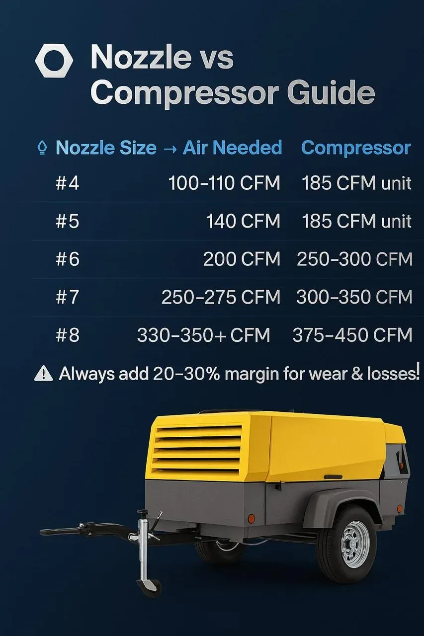
3. Start with the exact nozzle
Record nozzle manufacturer, model, nominal bore, nozzle material, inlet/thread arrangement and the supplier chart or technical source used for air consumption. Do not copy demand from an unrelated nozzle simply because nominal bore appears similar.
4. Use verified nozzle charts
Preserve chart revision, pressure basis and units beside every selected value.

5. Working pressure belongs at the nozzle system
Source pressure can be lost through treatment, valves, couplings, supply hose, blast machine and blast hose. The pressure relevant to blasting duty is the verified working condition at the appropriate downstream boundary using the equipment supplier's approved method.
6. Nozzle bore and demand
Use the verified chart for the exact nozzle and working pressure.
7. Nozzle wear changes the duty
Nozzle inspection is therefore an air-system issue as well as a consumable-maintenance issue.
8. Wear must be measured
Record actual bore or the manufacturer's approved wear indicator at controlled intervals. Do not assume nozzle age equals wear. Abrasive type, operating hours, nozzle material and working conditions can change wear rate.
9. Do not compensate for excessive wear with compressor capacity
If a worn nozzle has exceeded the supplier's service criterion, adding compressor capacity can hide the symptom while increasing energy and operating cost. Follow the nozzle manufacturer's inspection/replacement guidance.
10. Pressure and productivity boundary
Abrasive, surface condition, specification, nozzle technique, access and accepted quality influence output. Air supply is one governing input, not a guaranteed production-rate formula.
11. Surface-preparation specification
Record the actual project surface-preparation requirement and blast-equipment supplier instructions. Air-system selection should support the approved process without claiming that one compressor/nozzle combination guarantees a specified finish.
12. Single-nozzle demand
For one nozzle, use its verified consumption at the required pressure and state the flow reference basis. Add only identified auxiliary demands and justified system effects. Avoid an unexplained reserve percentage.
13. Multiple nozzles
For several operators, sum nozzle demand only for nozzles that can operate concurrently. Record credible simultaneous crews, shift practice and any sequencing constraints.
14. Worked example A — verified chart values
Illustrative method only. If a manufacturer's chart states that the selected nozzle requires Q1 at the required working pressure, one-nozzle design demand begins with Q1. For three truly simultaneous identical nozzles, nozzle demand begins with 3×Q1.
15. Worked example B — wear sensitivity
Illustrative method only. A new nozzle has verified chart demand Qnew. After measured wear, the actual bore corresponds to supplier demand Qworn. Incremental demand = Qworn − Qnew; percentage increase = (Qworn − Qnew)/Qnew ×100. Use actual supplier values, not an assumed wear factor.
16. Worked example C — concurrency
Illustrative only. Four blast stations are installed but operating records prove a maximum of three nozzles can run simultaneously. The demand case is based on three active nozzles plus identified auxiliaries, not automatically all four. If manual practice allows four, the assumption must be revised.
17. Worked example D — delivered pressure loss
Illustrative only. Source pressure is not nozzle pressure. If measured losses occur across treatment, main hose, blast machine and blast hose, the nozzle receives the remaining pressure. The engineering response is to quantify each loss and correct avoidable restrictions rather than blindly raising compressor pressure.
18. Flow reference basis
State whether nozzle-chart demand is FAD, standard/reference flow or another supplier basis. Compressor capacity must be compared on a compatible basis.
19. Gauge and absolute pressure discipline
Nozzle operating pressure is commonly discussed as gauge pressure, while gas calculations may require absolute pressure. Preserve the pressure basis.
20. Supply hose
Long, undersized or damaged supply hose can consume pressure. Record hose internal diameter, length, condition and routing. A large compressor cannot eliminate friction through an inadequate hose path.
21. Blast hose
Blast hose carries the air-abrasive stream and is part of the equipment system. Follow blast-equipment/nozzle supplier requirements for size, length, condition and connections.
22. Couplings and connectors
Restrictive, damaged or mismatched couplings can increase pressure loss and create reliability concerns. Use compatible rated equipment and inspect condition. Do not treat coupling bore as a trivial detail in a high-flow blasting path.
23. Blast machine / pot pressure loss
The blast machine, valves and metering arrangement contribute to the delivered pressure path.
24. Treatment pressure loss
Separators, aftercoolers, dryers and filters can improve air condition but consume pressure. Select treatment for actual flow and inlet condition and include its pressure loss in the delivered-air budget.
25. Moisture control
The required dryness should come from equipment and project specification. Do not assume one separator delivers every required condition.
26. Condensate management
High-volume portable or temporary systems can produce substantial condensate after cooling. Drain and treatment arrangements should prevent carryover into blasting equipment and follow site environmental requirements.
27. Compressor capacity comparison
Compare the compressor's supported delivered flow at the required operating condition with the compatible total demand basis. Do not select from engine power, nominal model class or an unrelated pressure rating.
28. Compressor pressure capability
The package must provide sufficient pressure to overcome documented system losses while maintaining the required nozzle condition. Higher package pressure is not automatically better and can increase energy/fuel use or exceed equipment limits.
29. Diesel versus electric boundary
Either source can be technically suitable if it meets the validated pressure-flow, treatment, control and site requirements.
30. Multiple compressor packages
Where packages operate in parallel, verify compatible controls, manifolding, check/isolation arrangements and delivered capacity. Do not simply add nameplate flows without confirming the operating architecture.
31. Manifold distribution
A manifold serving multiple blast lines must maintain acceptable pressure distribution at credible concurrency. Measure or calculate the governing path and avoid small common restrictions that throttle every nozzle.
32. Simultaneous auxiliary users
Identify air-operated blast controls, breathing-air equipment only where separately engineered, cleaning functions or other legitimate users. Do not hide auxiliaries inside an unexplained margin.
33. Breathing-air boundary
Breathing air requires an explicitly engineered and verified arrangement meeting applicable respirator instructions and occupational requirements. Ordinary process air, oil-free compression or a general filter alone does not establish suitability.
34. Carbon-monoxide and respiratory boundary
35. Abrasive media interaction
Media type and condition can affect flow through the blast system and accepted surface result. Use equipment supplier and project process requirements.
36. Nozzle blockage or unstable media flow
Do not diagnose every unstable blast stream as low compressor capacity. Check moisture, media condition, metering, nozzle condition, hose condition and equipment restrictions alongside delivered pressure.
37. Diagnostic — low nozzle pressure
Measure pressure at appropriate points under operating conditions. If compressor discharge remains stable while downstream pressure falls, locate loss across treatment, valves, couplings, hoses or blast equipment.
38. Diagnostic — pressure good with one nozzle, poor with two
This indicates a concurrency/delivery issue until proven otherwise. Compare total verified demand with source capacity and common distribution restrictions.
39. Diagnostic — rising air use over campaign
Inspect nozzle wear, leaks, hose/coupling condition and operating concurrency. A gradual demand increase can follow bore enlargement rather than compressor deterioration.
40. Diagnostic — wet media / poor flow
Check treatment, drains, ambient conditions, hose route and blast-machine condition. Restore moisture-control performance based on the actual process requirement.
41. Diagnostic — compressor appears large enough but output poor
Check delivered nozzle pressure, nozzle condition, media, surface specification, access and operator/process factors.
42. Nozzle replacement decision
Use the manufacturer's inspection and replacement criterion together with measured bore/condition and observed air demand. Do not set a universal replacement interval.
43. Long campaign planning
A long blasting campaign can accumulate substantial loaded compressor duty and nozzle wear even if originally arranged as a short project. Track operating hours, nozzle condition, treatment condition and maintenance needs.
44. Temporary-air tie-in
For rental supply, define source location, treatment, hose/manifold route, simultaneous crews and nozzle requirement.
45. Local storage boundary
Storage can support certain transient demands but abrasive blasting is often a sustained high-flow duty. A receiver cannot make an undersized source sustain continuous nozzle demand indefinitely.
46. Fuel and energy perspective
For diesel packages, compare supported fuel consumption under representative duty when available. For electric sources, use supported electrical input. Do not claim savings from nominal compressor size alone.
47. Cost per accepted work
These can support future job comparison more reliably than remembering only compressor size.
48. Commissioning — identity
Confirm nozzle make/model/bore, blast machine, hoses, couplings, treatment and compressor package against the approved duty before starting.
49. Commissioning — pressure
Verify delivered pressure under the governing active-nozzle combination using the approved equipment method.
50. Commissioning — treatment
Verify drains and required air condition under actual load. A treatment train that performs at idle may behave differently at full blasting flow.
51. Commissioning — repeatability
Observe stable operation over representative blasting duration and concurrent crews. Record nozzle condition and any pressure decay.
52. Acceptance
Acceptance should demonstrate the validated nozzle pressure-flow duty, acceptable air condition, stable supply at governing concurrency and correct equipment interfaces. Surface-quality acceptance remains with the project specification.
53. Required asset — purpose
The Nozzle Wear and Supply Demand Comparison links nominal and measured nozzle condition to verified supplier air demand and the delivered supply condition. It prevents nozzle wear from being hidden inside compressor oversizing.
54. Required asset — nozzle fields
Record nozzle make/model, material, nominal bore, measured bore/condition, operating hours, supplier chart/version, required working pressure and replacement criterion.
55. Required asset — demand fields
Record new-condition demand, worn-condition demand where supported, flow reference basis, simultaneous nozzle count, auxiliary demand, treatment/distribution losses and required source condition.
56. Required asset — measured performance
57. Required asset — decision
Classify whether the issue is nozzle wear, supply capacity, distribution loss, treatment/moisture, equipment restriction or unresolved. Record corrective action and post-action result.
Field guide
Blasting performance is decided at the air source
On site a blasting set-up looks simple: a diesel compressor, a hose across the ground, a blast pot and an operator. The finish is decided before the nozzle fires. When the air system is weak the failure is quiet: blasting slows, abrasive use rises, the profile turns uneven, coating adhesion falls and the schedule slips, while the operator keeps working.
Four layers that must all hold
- The compressor's mechanical condition. A worn machine gives pressure dips under continuous blasting, overheating in hot weather, poor fuel use and unexpected trips. Operator skill cannot make up for unstable air.
- Air quality. Moisture clumps abrasive, blocks nozzles, gives an irregular pattern, weakens coating adhesion and lets steel flash-rust after blasting. Use moisture separation, filtration, working drains and clean receivers.
- The delivery line. Long hoses over rough ground, reused couplings and mismatched bores each add resistance, and resistance is pressure lost. A set rated for high CFM at the compressor can deliver much less at the nozzle: slower blasting, more fuel, more labour hours and more abrasive. Treat the hose line as a pipeline.
- The blast pot. Metering valves, seals and pot design decide whether abrasive feed is steady. A worn pot gives a fluctuating pattern even from a perfect compressor.
Size for the nozzle you will have
Air demand follows nozzle diameter, nozzle wear, pressure, the number of operators and the hose size and length. As a nozzle wears its bore grows and it draws more air, so a compressor that suited a new nozzle can become short as it wears. Measure at the nozzle, not at the compressor gauge. Use the blasting air demand calculator, which has a worked example, and see temporary air for blasting.
Indian site conditions
- Summer heat stresses cooling systems.
- Monsoon humidity puts more water into the air line.
- Dusty construction zones load filters quickly.
- Moving between sites speeds up wear on hoses and couplings.
Equipment and hose choices should be made for those conditions rather than for a brochure's controlled environment.
The slow cost of a weak air system
Longer projects, more abrasive, more fuel, extra labour hours, rework, coating failures and downtime rarely arrive as one big failure. They add up quietly, and across projects can exceed the price of a better set-up. If blasting feels slower than it should, abrasive use is high or coatings fail later, check the air system before blaming operator technique.