
What this calculation answers
Blasting is a sustained, near-continuous air load. The question is not whether a compressor can reach 7 bar with the blast valve closed, but whether it can hold the required nozzle pressure while every nozzle on the job is flowing, through a shift, in site conditions. This page gives a worked table method you can fill in by hand or in a spreadsheet. It produces three numbers:
- Total air demand in cfm (or m³/min) at the working nozzle pressure.
- Required compressor working pressure at the discharge.
- A compressor size, or combination of compressors, with a sensible margin.
It calculates air demand only. It does not predict blasting rate, surface finish or abrasive consumption; those depend on abrasive, technique, substrate and the coating specification.
Step 1: nozzle demand from the chart
Start with the nozzle you will actually use. Nozzle numbers give the bore in sixteenths of an inch. The table shows rounded typical values from widely published industry charts for new nozzles; your nozzle maker’s chart takes priority.
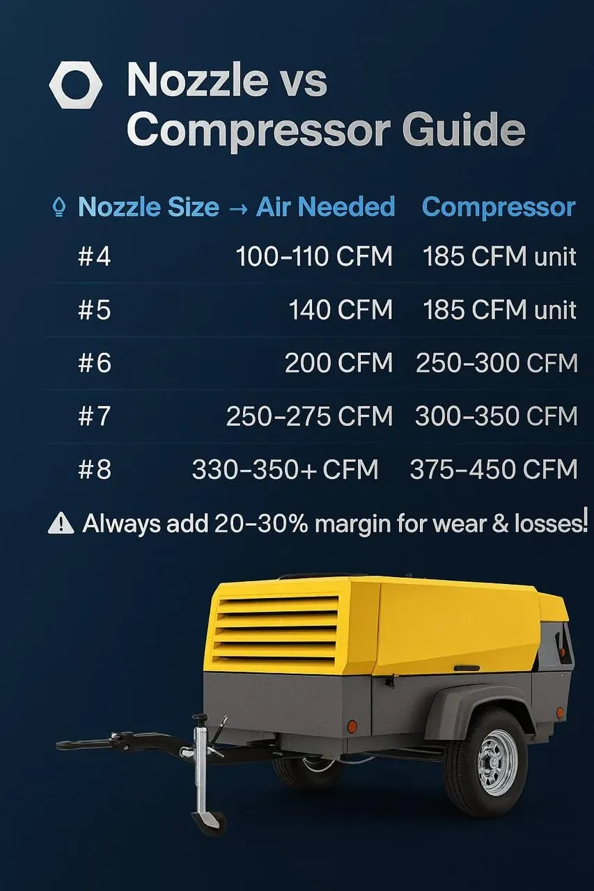
| Nozzle no. | Bore | Typical cfm at 5.5 bar (79.8 psig) | Typical cfm at 7 bar (101.5 psig) |
|---|---|---|---|
| No. 3 | 3/16 in (4.8 mm) | about 55 | about 65–70 |
| No. 4 | 1/4 in (6.4 mm) | about 110 | about 130–140 |
| No. 5 | 5/16 in (8.0 mm) | about 165 | about 195–210 |
| No. 6 | 3/8 in (9.5 mm) | about 235 | about 280–300 |
| No. 7 | 7/16 in (11.1 mm) | about 320 | about 380–410 |
| No. 8 | 1/2 in (12.7 mm) | about 420 | about 500–540 |
Record the chart’s flow basis (free air, cfm or m³/min) and pressure basis (gauge pressure at the nozzle). Do not mix a chart in m³/min with a compressor rated in cfm without converting: 1 m³/min is about 35.3 cfm.
Step 2: correct for pressure and wear
If your target pressure or bore is not on the chart, a nozzle behaves broadly like a choked orifice, so flow scales with bore area and absolute upstream pressure:
Q₂ ≈ Q₁ × (d₂ ÷ d₁)² × (P₂ + 1.013) ÷ (P₁ + 1.013), with P in bar gauge.
This is an estimate for checking and for wear allowance, not a substitute for the maker’s chart. Examples using a No. 6 at 290 cfm, 7 bar:
- At 6 bar: 290 × 7.013 ÷ 8.013 ≈ 254 cfm.
- Worn by 1/16 in to 7/16 in bore at 7 bar: 290 × (11.1 ÷ 9.5)² ≈ 396 cfm, close to a new No. 7.
That second line is why wear matters. A common industry rule is to replace a nozzle once the bore has grown about 1/16 in (1.6 mm). Unless replacement is strictly controlled, size the compressor for one nozzle number larger than the new nozzle.
Step 3: add every other air user
| User | Where the figure comes from |
|---|---|
| Supplied-air respirators | Respirator maker’s flow per operator, through a dedicated breathing-air system |
| Pot remote controls and pressurising | Small; covered by the margin in most cases |
| Air tools (grinders, needle scalers) | Tool maker’s consumption at working pressure, times usage factor |
| Vacuum recovery or dust collector pulse cleaning | Equipment maker’s data |
| Blow-down nozzles for cleaning surfaces | Treat as a small nozzle if used during blasting |
Count nozzles that genuinely run at the same time. On blasting jobs, simultaneity is usually close to 100% for each active crew; do not apply a diversity factor unless crews really take turns.
Step 4: working pressure at the compressor
Add the losses between compressor and nozzle to the nozzle pressure. Typical budget for a reasonable set-up:
- Aftercooler and moisture separator: about 0.2–0.5 bar.
- Supply hose and couplings: depends on bore and length; 0.2–0.5 bar on a short, correctly sized run.
- Blast pot inlet, piping and metering valve: about 0.3–0.5 bar.
- Blast hose: often 0.5 bar or more on long runs.
For a 7 bar nozzle, this usually puts the compressor working pressure at 8.5–10 bar (123.3–145 psig). Confirm on site by measuring with a needle gauge at the nozzle. Each extra bar of compressor discharge pressure typically costs about 7% more power, so reducing losses is usually better than raising pressure. Keep the compressor’s maximum below the blast pot’s rating, or protect the pot with a rated regulator and relief device.
Step 5: choose the compressor
Compare the total demand with the compressor’s delivered flow (free air delivery) at the working pressure, not its maximum flow at a lower pressure. Add a margin of about 10–20% for high ambient temperature, altitude, gradual wear and future additions. Then map the result to a size class.
| Total demand | Typical portable class |
|---|---|
| up to about 200 cfm | 185–250 cfm class |
| 200–350 cfm | 250–400 cfm class |
| 350–550 cfm | 400–600 cfm class |
| above 550 cfm | larger single unit or two or more compressors on a manifold |
Worked example: two No. 6 nozzles on a tank job
A contractor plans two crews blasting a storage tank, each with a No. 6 nozzle at 7 bar (101.5 psig), two supplied-air respirators and occasional grinder use. Figures for respirators and grinder below are illustrative; use your equipment makers’ data.
| Line | Item | Basis | cfm |
|---|---|---|---|
| 1 | 2 × No. 6 nozzles, new | 2 × 290 at 7 bar | 580 |
| 2 | Wear allowance to No. 7 equivalent | 2 × (396 − 290) | 212 |
| 3 | Respirators (illustrative) | 2 × 20 | 40 |
| 4 | Grinder, 25% of time (illustrative) | 40 × 0.25 | 10 |
| 5 | Sub-total | lines 1–4 | 842 |
| 6 | Margin for heat, altitude, controls | 10% | 84 |
| 7 | Required delivered air | line 5 + line 6 | about 925 |
| 8 | Compressor working pressure | 7 bar + about 1.5–2 bar losses | 8.5–9 bar (123.3–130.5 psig) |
Result: about 925 cfm at 8.5–9 bar. Practical options are one compressor of roughly 900–1,000 cfm in that pressure class, or two compressors of about 450–500 cfm each, one per crew. Without the wear allowance, two new No. 6 nozzles need about 600–750 cfm. Two units add resilience: if one stops, one crew keeps working. If the contractor commits to changing nozzles strictly at 1/16 in wear, line 2 can shrink, but the crews must then actually gauge and replace nozzles.
Checking the result on site
A calculation is a starting point. On the first day of blasting, confirm it with three measurements taken while all nozzles are flowing: pressure at the compressor discharge, pressure at the blast pot inlet, and nozzle pressure with a needle gauge just behind the nozzle. If nozzle pressure is below target while the compressor is at full load, the job is short of air; if the compressor unloads often and nozzle pressure is still low, the losses are in the hose, treatment or pot. Repeat the nozzle bore check every few days on heavy jobs and update line 2 of the table if wear is faster than planned. Keeping these readings also makes it much easier for us to advise quickly if production falls.
Common calculation mistakes
- Using compressor maximum flow at 7 bar when it must work at 9 bar.
- Sizing for new nozzles only and finding the job short of air by the second week.
- Forgetting respirators, which must be fed from a proper breathing-air system.
- Mixing m³/min and cfm, or gauge and absolute pressure.
- Reading pressure at the compressor gauge instead of at the nozzle.
- Assuming a bigger compressor fixes undersized hose; it often does not.
How Reddy Compressors helps
Sandblasting air is a core part of our business, not a side line. Over the years we have supplied many compressors for sandblasting, both as outright sales and on hire, to painting, coating and surface-preparation contractors and to plants doing their own maintenance blasting. That experience shapes how we size, equip and service every blasting package we send out.
Send us your nozzle sizes and job details and our engineers in Secunderabad will check the calculation and propose a compressor package. As an independent multi-brand specialist, we sell, rent and service ELGi, Atlas Copco, Ingersoll Rand, KAESER, Chicago Pneumatic, Doosan and other makes. Our rental fleet covers 50–2,000 cfm and 2–30 bar, diesel and electric, with aftercoolers, moisture separators, hoses and dryers. Service teams cover all of Telangana and Andhra Pradesh, and we supply across India. See sandblasting compressor hire.
What to send us
- Nozzle numbers, measured bores and the chart you are using.
- Target nozzle pressure and number of crews blasting at once.
- Respirators, tools and other air users.
- Hose lengths and bores, blast pot make and rating.
- Site location, ambient conditions and job duration.
Frequently asked questions
How do I calculate cfm for sandblasting?
Read the nozzle’s air consumption from its manufacturer’s chart at the pressure you need at the nozzle, typically 7 bar (101.5 psig). Multiply by the number of nozzles running together, allow for wear by using one nozzle size larger, add respirators and tools, then add a margin of about 10–20%. Choose a compressor that delivers that total at the required working pressure.
How much air does a No. 7 blasting nozzle use?
Typical industry charts show a new No. 7 (7/16 in, 11.1 mm) nozzle using about 380–410 cfm at 7 bar (101.5 psig) at the nozzle, and roughly 320 cfm at 5.5 bar (79.8 psig). Worn nozzles use more. Use your nozzle maker’s chart for the final figure, and size the compressor in the 400–600 cfm class or above with a margin.
How does nozzle wear affect compressor size?
Air demand rises with the square of the bore. A No. 6 nozzle worn by 1/16 in behaves roughly like a new No. 7 and can need over a third more air. If nozzles are not gauged and replaced on time, a compressor sized for new nozzles will fall short and nozzle pressure will drop. Allow one nozzle size of wear unless replacement is tightly controlled.
What compressor pressure do I need for 100 psi at the nozzle?
Typically 125–150 psig (8.6–10.3 bar) at the compressor, to cover losses in the aftercooler, separator, supply hose, blast pot and blast hose. The exact figure depends on hose bore and length. Measure with a needle gauge behind the nozzle while blasting, and keep the compressor’s maximum pressure within the blast pot’s rating or protect the pot with a rated regulator.
Can I use this method for wet blasting or blast cabinets?
The same principle applies, flow from the maker’s data at the working pressure plus other users, but suction cabinets, wet blasting and specialist media systems have different air characteristics. Use the equipment manufacturer’s consumption figures for that system rather than pressure-blast nozzle charts. Send us the equipment details and we can check the compressor selection for you.
Related pages
Calculators and worked examples
These tools give indicative figures for screening, comparison and for preparing an enquiry. They run in your browser and send nothing. No prices or tariffs are assumed: enter your own to see costs. Efficiencies and other figures shown are example values: replace them with your own. Results are not a performance guarantee or a design certificate; final selection is confirmed by a service engineer against the machine data sheet and the site.
Abrasive blasting air demand
The worked example below shows the method with fixed numbers. Turn on JavaScript to change the inputs.
Worked example
Inputs
- Nozzle bore (mm): 8
- Pressure at the nozzle (bar g): 7
- Discharge coefficient: 0.9
- Number of nozzles: 1
- Allowance for pot, hose and leaks (%): 10
Result
- Air demand, new nozzle: 4.69 m³/min = 166 cfm
- Nozzle number (bore in 1/16 inch): 5
- Air demand when worn one size (1/16 in larger bore): 6.74 m³/min = 238 cfm: size the compressor for this, then replace the nozzle
Method. Nozzle air treated as orifice flow at the nozzle pressure: free air = Cd × A × choked mass flow ÷ ρ₀. Venturi nozzles with an effective Cd near 0.9 are typical; use the supplier value. Add flow for the pot and for leaks. Nozzle numbers are the bore in sixteenths of an inch (No. 6 = 3/8 in = 9.5 mm). A nozzle wears larger in use, so size the compressor for the nozzle worn one size and replace it at that point.
What to take from it. A worn nozzle passes more air for less work. Check bore wear and keep the pressure at the nozzle, not at the compressor.
Technical content reviewed by D. Srinivas Reddy, Managing Partner and service engineer, Reddy Compressors. Last updated 17 October 2026. How our engineering content is reviewed.